Advertisement
Table of Contents
INDOOR UNIT
SERVICE MANUAL
Models
MSY-TP35VF
MSY-TP50VF
-
E1
ET1
,
-
E1
ET1
,
CONTENTS
1. TECHNICAL CHANGES ··································· 3
2. PART NAMES AND FUNCTIONS ····················· 4
3. SPECIFICATION ················································ 5
4. NOISE CRITERIA CURVES ······························ 6
5. OUTLINES AND DIMENSIONS ························ 7
6. WIRING DIAGRAM ············································ 8
7. REFRIGERANT SYSTEM DIAGRAM ··············· 9
8. SERVICE FUNCTIONS ··································· 10
9. MICROPROCESSOR CONTROL ····················11
10. TROUBLESHOOTING ····································· 17
11. DISASSEMBLY INSTRUCTIONS ···················· 27
PARTS CATALOG (OBB816)
No. OBH816
Outdoor unit service manual
MUY-TP·VF Series (OBH817)
Advertisement
Table of Contents

Subscribe to Our Youtube Channel
Related Manuals for Mitsubishi Electric MUY-TP-VF Series


Summary of Contents for Mitsubishi Electric MUY-TP-VF Series
-
Page 1: Table Of Contents
INDOOR UNIT No. OBH816 SERVICE MANUAL Models MSY-TP35VF MSY-TP50VF Outdoor unit service manual MUY-TP·VF Series (OBH817) CONTENTS 1. TECHNICAL CHANGES ··································· 3 2. PART NAMES AND FUNCTIONS ····················· 4 3. SPECIFICATION ················································ 5 4. NOISE CRITERIA CURVES ······························ 6 5. OUTLINES AND DIMENSIONS ························ 7 6. - Page 2 Use the specified refrigerant only Never use any refrigerant other than that specified. Doing so may cause a burst, an explosion, or fire when the unit is being used, serviced, or disposed of. Correct refrigerant is specified in the manuals and on the spec labels provided with our products. We will not be held responsible for mechanical failure, system malfunction, unit breakdown or accidents caused by failure to follow the instructions.
-
Page 3: Technical Changes
TECHNICAL CHANGES MSY-TP35VF - MSY-TP50VF - 1. New model OBH816... -
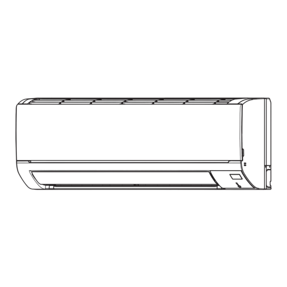
Page 4: Part Names And Functions
PART NAMES AND FUNCTIONS MSY-TP35VF MSY-TP50VF Air inlet Front panel Air filter Horizontal vane Air outlet Heat exchanger Remote control receiving section Operation indicator lamp Emergency operation switch ACCESSORIES Installation plate Installation plate fixing screw 4 × 25 mm Felt tape (Used for left or left-rear piping) OBH816... -
Page 5: Specification
SPECIFICATION Indoor model MSY-TP35VF MSY-TP50VF Power supply Single phase 230 V, 50 Hz Breaker Capacity Power input 1 (Total) Cooling 1,450 Running current 1 Cooling (Total) Power factor 1 (Total) Cooling Starting current 1 (Total) Model RC0J30-MD Current Cooling 0.32 Dimensions W ×... -
Page 6: Noise Criteria Curves
NOISE CRITERIA CURVES MSY-TP35VF MSY-TP50VF FAN SPEED FUNCTION SPL(dB(A)) LINE FUNCTION SPL(dB(A)) FAN SPEED LINE Super High Super High COOLING COOLING NC-70 NC-70 NC-60 NC-60 NC-50 NC-50 NC-40 NC-40 NC-30 NC-30 NC-20 NC-20 NC-10 NC-10 1000 2000 4000 8000 1000 2000 4000 8000... -
Page 7: Outlines And Dimensions
OUTLINES AND DIMENSIONS MSY-TP35VF MSY-TP50VF Unit: mm Insulation Ø50 O.D Liquid line Ø8 - 0.5m (Flared connection Ø6.35) Gas line Ø12 - 0.45m (Flared connection Ø9.52) Drain hose Insulation Connected part Ø16 O.D OBH816... -
Page 8: Wiring Diagram
WIRING DIAGRAM MSY-TP35VF - MSY-TP50VF - MSY-TP35VF - MSY-TP50VF - PARÇA ADI SİGORTA (T3.15AL250V) TERMİK SİGORTA 4.5A Ý DIŞ ÜNİTEYE FAN MOTORU KANAT MOTORU (YATAY) VARİSTÖR GÜÇ KAYNAĞI İÇ ÜNİTE GÜÇ REAKTÖR KARTI SİGORTA ODA SICAKLIK TERMİSTÖRÜ BORU SICAKLIK TERMİSTÖRÜ(ANA) BORU SICAKLIK TERMİSTÖRÜ(YARDIMCI) : 1. -
Page 9: Refrigerant System Diagram
REFRIGERANT SYSTEM DIAGRAM MSY-TP35VF MSY-TP50VF Unit: mm Refrigerant pipe ø9.52 (with heat insulator) Indoor coil Indoor thermistor heat RT12 exchanger Flared connection Indoor coil thermistor RT13 Room temperature thermistor RT11 Flared connection Refrigerant pipe ø6.35 (with heat insulator) Refrigerant flow in cooling OBH816... -
Page 10: Service Functions
SERVICE FUNCTIONS MSY-TP35VF MSY-TP50VF 8-1. TIMER SHORT MODE For service, the following set time can be shortened by bridging the timer short mode point on the electronic control P.C. board. (Refer to 10-7.) Set time : 3-minute → 3-second (It takes 3 minutes for the compressor to start operation. However, the starting time is shortened by bridging the timer short mode point.) NOTE: While the relay 52C is ON, the compressor starting time cannot be shortened. -
Page 11: Microprocessor Control
MICROPROCESSOR CONTROL MSY-TP35VF MSY-TP50VF WIRED REMOTE CONTROLLER (Option : Example) PAR-33MAA The main display can be displayed in 2 different modes: "Full" and "Basic." Display The initial setting is "Full." 1 Operation mode Appears when the On/Off timer or Night setback Indoor unit operation mode appears here. - Page 12 Menu structure Press button. Main menu Move the cursor to the desired item with buttons, and press button. Vane · Louver · Vent. (Lossnay) High power Timer ON/OFF timer Auto-OFF timer Weekly timer Restriction Temp. range Operation lock Energy-saving Auto return Schedule Night setback Filter information...
- Page 13 Main menu list Setting and display items Setting details Vane · Louver · Vent. Use to set the vane angle. • Select a desired vane setting from 5 different settings. (Lossnay) Use to turn ON/OFF the louver. Not available Use to set the amount of ventilation. Not available High power Use to reach the comfortable room temperature quickly.
- Page 14 INDOOR UNIT DISPLAY SECTION Operation Indicator lamp The operation indicator at the right side of the indoor unit indicates the operation state. •The following indication applies regardless of shape of the indication. Indication Operation state Room temperature The unit is operating to About 2°C or more away reach the set temperature.
- Page 15 9-3. FAN( )OPERATION (1) Press button. OFF/ON lamp will light up in green and the operation will start. (2) Select FAN mode with button. (3) Press button to select the desired fan speed. When AUTO, it becomes Low. Only indoor fan operates. Outdoor unit does not operate. Press button to go through the fan speeds in the following order.
- Page 16 (4) VANE AUTO ( ) mode In VANE AUTO mode, the microprocessor automatically determines the vane angle to make the optimum room tempera- ture distribution. In COOL and DRY operation Vane angle is fixed to Horizontal position. Horizontal position (5) STOP (operation OFF) and ON TIMER standby In the following cases, the horizontal vane returns to the closed position.
-
Page 17: Troubleshooting
TROUBLESHOOTING MSY-TP35VF MSY-TP50VF 10-1. CAUTIONS ON TROUBLESHOOTING 1. Before troubleshooting, check the following: 1) Check the power supply voltage. 2) Check the indoor/outdoor connecting wire for miswiring. 2. Take care of the following during servicing 1) Before servicing the air conditioner, be sure to turn OFF the main unit first with the remote controller, and then after confirming the horizontal vane is closed, turn OFF the breaker and/or disconnect the power plug. - Page 18 10-2. FAILURE MODE RECALL FUNCTION Outline of the function This air conditioner can memorize the abnormal condition which has occurred once. Even though LED indication listed on the troubleshooting check table (10-4.) disappears, the memorized failure details can be recalled. This mode is very useful when the unit needs to be repaired for the abnormality which does not recur.
- Page 19 10-3. INSTRUCTION OF TROUBLESHOOTING Start Indoor unit oper- Indoor unit does OPERATION INDICATOR not receive ates. lamp on the indoor unit is the signal from Outdoor unit blinking on and off. does not operate. remote controller. If blinking of OPERATION INDI- CATOR lamp cannot be checked, it can be checked with failure Outdoor unit...
- Page 20 10-4. TROUBLESHOOTING CHECK TABLE Before taking measures, make sure that the symptom reappears for accurate troubleshooting. When the indoor unit has started operation and detected an abnormality of the following condition (the first detection after the power ON), the indoor fan motor turns OFF and OPERATION INDICATOR lamp blinks. OPERATION INDICATOR Blinking Not lit...
- Page 21 10-5. TROUBLE CRITERION OF MAIN PARTS MSY-TP35VF MSY-TP50VF Part name Check method and criterion Figure Measure the resistance with a tester. Room temperature thermistor (RT11) Refer to 10-7. "Test point diagram and voltage", "2. Indoor electronic control Indoor coil thermistor P.C.
- Page 22 10-6. TROUBLESHOOTING FLOW A Check of indoor fan motor The indoor fan motor error has occurred, and the indoor fan does not operate. Turn OFF the power supply. Pay enough attention to the high voltage on the fan motor connector CN211. Turn ON the power supply, wait 5 seconds or more, and then press EMERGENCY OPERATION switch.
- Page 23 B Check of indoor P.C. board and indoor fan motor Turn OFF the power supply. Remove indoor fan motor connector CN211 from indoor power P.C. board and vane Measure the resistance of indoor fan Short circuit: motor connector CN151 from the indoor motor.
- Page 24 C How to check miswiring and serial signal error Turn OFF the power supply. Is there rated voltage in the Check the power supply. power supply? 1. Turn ON the power supply. 2. Press the emergency operation switch. Has the relay 52C been turned on 3 minuets later ? NOTE: Use the wireless remote controller of [The relay will be turned on in 3 to 7 seconds by...
- Page 25 D Electromagnetic noise enters into TV sets or radios Is the unit earthed? Earth the unit. Is the distance between the antennas Extend the distance between the antennas and and the indoor unit within 3 m, or is the the indoor unit, and/or the antennas and the distance between the antennas and the outdoor unit.
- Page 26 10-7. TEST POINT DIAGRAM AND VOLTAGE MSY-TP35VF MSY-TP50VF 1. Indoor power P.C. board 12 V DC 5 V DC Connector to indoor electronic Indoor terminal block Indoor terminal block control P.C. board (CN20A) connecting (TAB2) connecting (TAB1) Connector to Terminal block (CN201) Fuse (F11) T3.15AL250V...
-
Page 27: Disassembly Instructions
DISASSEMBLY INSTRUCTIONS <Detaching method of the terminal with locking mechanism> The terminal which has the locking mechanism can be detached as shown below. There are following 2 types of the terminal with locking mechanism. The terminal without locking mechanism can be detached by pulling it out. Check the shape of the terminal before detaching. - Page 28 OPERATING PROCEDURE PHOTOS/FIGURES 2. Removing the indoor power P.C. board and the Photo 2 electrical box Water cover (1) Remove the panel. (Refer to section 1.) Remove the right corner box. Screws of the earth plate (2) Disconnect the following connectors: Screw of the <Indoor electronic control P.C.
- Page 29 OPERATING PROCEDURE PHOTOS/FIGURES 3. Removing the indoor electronic control P.C. Photo 4 board Control P.C. board holder (Inside) (1) Remove the panel. (Refer to section 1.) Remove the right Catch corner box. Indoor electronic (2) Disconnect the following connectors: control P.C. board <Indoor electronic control P.C.
- Page 30 OPERATING PROCEDURE PHOTOS/FIGURES 5. Removing the indoor fan motor, the indoor coil Photo 6 thermistor and the line flow fan (1) Remove the panel. (Refer to section 1.) Remove the corner box. (2) Remove the control P.C. board holder, the water cover, the electrical box and the nozzle assembly.
- Page 31 Fixing the indoor coil thermistor There are 2 forms of parts for fixing the indoor coil thermistor. When fixing the indoor coil thermistor to the clip-shape/holder-shape part, the Clip shape Holder shape lead wire should point down. About the same length Position and procedure for mounting the clip-shape part 1.
- Page 32 HEAD OFFICE: TOKYO BUILDING, 2-7-3, MARUNOUCHI, CHIYODA-KU, TOKYO 100-8310, JAPAN © Copyright 2018 MITSUBISHI ELECTRIC CORPORATION Published: Oct. 2018. No. OBH816 Made in Japan Specifications are subject to change without notice.
Need help?
Do you have a question about the MUY-TP-VF Series and is the answer not in the manual?
Questions and answers