Advertisement
Quick Links
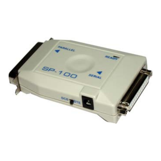
PS-100/SP-100
Parallel to Serial or
Serial to Parallel
Converters
User's Manual
1-1 PS-100/SP-100 INTRODUCTION
The PS-100/SP-100 one-way converter is a low
cost converter device. The purpose of the device
is either to convert a parallel (Centronics) inter-
face into a Serial (RS-232C) interface or to con-
vert a Serial interface into a parallel interface. The
main difference between the PS-100 and the SP-
100 is that the PS-100 converts parallel signal to
serial signal and the SP-100 converts serial signal
to parallel signal.
1-2 Operation
The operation and installation of the PS-100/SP-
100 are very simple and easy. For the PS-100, the
user only needs a 25-pin to 36-pin cable linked
from DEVICE A parallel port LPT1 (or LPT2) to
PS-100 parallel port, then plug in the PS-100 Se-
rial ports directly to DEVICE B Serial port.Finally
plug in the power adapter plug into the PS-100
power jack. For the SP-100, the user only needs a
25-pin to 25-pin cable linked from DEVICE C
serial port COM1(or COM2) to SP-100's serial
port, then plug the SP-100's parallel port directly
to DEVICE D. Finally, plug in the power adapter
plug into the SP-100 power jack.
1-3 CONFIGURING THE PS-100/SP-100
1. Gather all the information you can about the
serial port and the parallel port on the host and
peripheral.
2. Power off the devices which you are going
to connect with.
3. Setup the DIP switches on the converter ac-
cording to the serial information. (transmission
Baud rate, data length, stop bit and parity
check.)
4. Slide the DTE/DCE switch to cooperate with
the serial device. (See Note 2)
5. Connect converter to host and peripheral with
suitable extension cables.
6. Plug in the power plug head of the power
adapter into the power jack of PS-100/SP-100.
7. Turn on all the connected devices. The con-
verter will be ready to work.
PS: After you setup a new DIP SWITCH SET-
TING, you have to press the "Reset Button."
Then the Ready LED will flash twice, indicat-
ing the unit has started running the new set-
tings.
1-4 PS100/SP100 SPECIFICATIONS
Function
Power Adapter
Serial Port(DCE)
Parallel Port
Interface Direction
Reset Key
Indicator(LED)
Hands hake
Baud Rate
Data Bits
Parity Bits
Driving Ability
Enclosure
W eight
Dimension
Specification
AC9V, 300mA
RS-232C, DB25 Female
Centronics, 36-pin Male
P → S, S → P
Res et Buffer System
Dis play System Status
Hardware and Xon-Xoff
from 300,....,9600, to 19200
7 bits or 8 bits
None, Even or Odd
Up to9M(30ft)
Plastic
220 grams
68W ×125L×20H mm
Advertisement

Related Manuals for CTC Union PS-100


Summary of Contents for CTC Union PS-100
- Page 1 1-2 Operation 1-4 PS100/SP100 SPECIFICATIONS The operation and installation of the PS-100/SP- Function Specification 100 are very simple and easy. For the PS-100, the Power Adapter AC9V, 300mA user only needs a 25-pin to 36-pin cable linked Serial Port(DCE) RS-232C, DB25 Female...
- Page 2 010 → 1200 001 → 2400 2) The mode of the serial port of SP-100/ 000 → 4800 3. Data BITS PS-100 is compatible with DTE or DCE OFF=8 5. Parity Type mode. Normal connection to PC with one to...