Advertisement
Quick Links
Advertisement

Subscribe to Our Youtube Channel
Related Manuals for Contacta STS-K015-01

Summary of Contents for Contacta STS-K015-01
- Page 1 Speech Transfer System STS-K015-01 Installation & User Guide August 2016 v1.0...
- Page 2 Important Safety Instructions Read these instructions. 2. Keep these instructions. 3. Heed all warnings. 4. Follow all instructions. 5. Do not use this apparatus near water. 6. Clean only with dry cloth. 7. Do not block any ventilation openings. Install in accordance with the manufacturer’s instructions.
- Page 3 Safety Precautions Thank you for purchasing this system. Before using, please read the following guide to ensure correct usage. After reading, store this guide in a safe place for future reference. Incorrect handling of this product could possibly result in personal injury or physical damage. The manufacturer assumes no responsibility for any damage caused by mishandling that is beyond normal usage defined in this manual.
-
Page 4: Table Of Contents
Installation Instructions Connections Engineer Mode Initial Set-Up Troubleshooting Contacta has a policy of continuous product development, and therefore small specification changes may not be reflected in this manual. Images, labels, packaging, accessories and product colours are subject to change without notice. -
Page 5: Product Overview
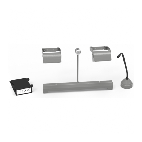
Product Overview Speech transfer systems provide assistance for clear communication where normal speech is impaired by use of glass, a security screen or other similar barriers. There is also a hearing loop facility included which provides additional assistance for hearing device wearers. Components 1. -
Page 6: Tools Required
Tools Required Your basic toolkit will include: • Screwdrivers (Flat or Blade 2.5mm • Pliers and Phillips Head PH2) • Tape Measure • Battery or Mains Drill • Pencil or Marker Pen • Drillbits: 2mm, 3mm, 5mm and 7mm • Torch •... -
Page 7: Installation Instructions
Installation Instructions Install the Staff Microphone, Amplifier, Overhead Loudspeakers, Bridge Bar Unit and Surface Mic in the order described below. If you have followed the steps closely and the system is not functioning as intended, consult Troubleshooting on page 14. Staff Microphone, Amplifier and Overhead Loudspeakers Fixing points Place the staff microphone on the staff side of the counter top, ensuring... - Page 8 5. Install the overhead loudspeakers: a. Find a location on the staff side directly above the pass-through tray. Ensure there is sufficient Fixing space and there is no glass points behind where you want to drill. b. Check the cable route to the amplifier situated under the counter. Ensure access through the counter top and suitable cable length.
- Page 9 Hearing Loop Installation The aerial should be fixed under the desk-top or counter centrally on the customer side, one half mounted horizontally under the counter and the other half mounted vertically, facing the customer (as in the first scenario below). Position the aerial under the counter using either the provided P-clips or another fixing method of your choice.
-
Page 10: Connections
Connections Trim the cables if necessary (apart from the power supply) to the required length for connection to the back of the amplifier. Bare approximately 6mm of the cable ends for connection to the 2 pin plugs (see diagram below). Rear Amplifier Connections Connect all green plugs to the back of the amplifier, observing the correct locations printed about the sockets (see below diagram). -
Page 11: Engineer Mode
Increase and decrease S t a t u s V o l I n V o l O u t S T S - A 3 1 contacta On/Off Settings c o n t a c t a Vol In... - Page 12 Setup Areas Whilst in Engineer Mode, there are 3 editable Setup Areas. You will always enter Setup Area 1 first. The green LED will flash to indicate which Setup Area you are in. Setup Area 1: Setup Area 2: Maximum Volume Adjustment Ducking Adjustment Set the maximum volume using Turn on/off and increase/decrease...
-
Page 13: Initial Set-Up
Factory Default Settings To return to the factory default settings: Unplug the power supply and then reconnect it. 2. Press the “On/Off” button and Volume In - button together, then release. 3. The status LED bar graph will show a fixed pattern of LEDs indicating the firmware revision number, followed by all LEDs illuminated - this indicates that the default settings have been restored. -
Page 14: Troubleshooting
1) Switch off any air con systems, desktop 1) Ambient noise in area is too high. into power saving fans and or computers to reduce ambient mode. noise. If no action is successful please seek assistance from your distributor or a Contacta installer. - Page 16 Contact your local distributor for further information. www.contacta.co.uk...
Need help?
Do you have a question about the STS-K015-01 and is the answer not in the manual?
Questions and answers