Advertisement
EBTRON
a measurable difference!
AIR-IQ PROBE
INTERNAL MOUNT INSTALLATION
OVERVIEW
This document provides the instructions necessary
to install AIR-IQ Internal Mount Probes as shown in
Figure 1. Internally mounted probes are installed
inside of the damper sleeve. Installation consists of
installing and securing the probes. For detailed
probe information, refer to the Duct/Plenum Probe
technical manual TM_GP1 under separate cover.
For detailed information on transmitter set up and
operation of the complete airflow measurement
station, refer to the associated transmitter technical
manual under separate cover.
AIR-IQ INTERNAL MOUNTING
Figure 2 provides AIR-IQ Internal Mount probe
installation details. Probes are installed from inside
of the damper sleeve using the included brackets.
AIR-IQ Internal mount probes are manufactured
shorter to permit 0.75 in (19 mm) adjustment and
allow for installation clearance. Convenient check
boxes are provided at each step.
1. Loosen the Non-Cable End Adjustment Screws on both sides of the probe as shown in the detail of Figure 2
for AIR-IQ Probes to permit pivoting the probe and bracket.
2. Carefully place the Non-Cable End bracket at the non cable end previously prepared location on the inside of
the damper sleeve wall so that when the probe is installed, airflow will be in the direction of the arrows printed on
the bracket and/or probe. For ease of installation, the probe can pivot within the bracket after loosening the Non-
Cable End Adjustment screws (completed in step 1).
If the airflow direction labels are not visible on the bracket and/or probe, orient the probe
so that the sensor SET SCREWS (two per sensor insert) face the DOWNSTREAM airflow
direction. (There are no setscrews on the upstream side of the sensor inserts).
3. Fasten the Non-Cable End mounting bracket to the damper sleeve at two places with appropriate field
supplied fasteners, again making sure that printed airflow arrows on the bracket and/or probe are in the actual
direction of duct air flow.
4. Carefully route the probe cable through the cable exit hole, and pivot the cable end probe bracket to the
previously prepared location on the damper sleeve wall.
5. Fasten the cable end mounting bracket to the damper sleeve at two places with appropriate field supplied
fasteners, again making sure that printed airflow arrows on the bracket and/or probe are in the actual direction of
duct air flow.
6. Slightly loosen the cable end probe Adjustment screws on both sides of the probe to permit probe movement
within the bracket.
EBTRON, Inc. 1663 Hwy. 701 S., Loris SC 29569 • Toll Free: 800.2EBTRON (232.8766) • Fax: 843.756.1838 •
®
NOTE:
A
-IQ P
IR
ROBES
Q
I
UICK
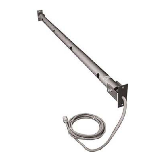
Figure 1. AIR-IQ Internal Mount Probe
- I
M
NTERNAL
OUNT
G
NSTALLATION
UIDE
Document Number 930-0036
www.EBTRON.com
1
Advertisement
Table of Contents

Related Manuals for Ebtron AIR-IQ


Summary of Contents for Ebtron AIR-IQ
- Page 1 6. Slightly loosen the cable end probe Adjustment screws on both sides of the probe to permit probe movement within the bracket. EBTRON, Inc. 1663 Hwy. 701 S., Loris SC 29569 • Toll Free: 800.2EBTRON (232.8766) • Fax: 843.756.1838 • www.EBTRON.com...
- Page 2 0.25 in. [6.35 mm] 0.188 in. [ 4.76 mm] Mtg. Holes (2) Figure 2. AIR-IQ Internal Mount Probe Mechanical Detail EBTRON, Inc. 1663 Hwy. 701 S., Loris SC 29569 • Toll Free: 800.2EBTRON (232.8766) • Fax: 843.756.1838 • www.EBTRON.com ...
Need help?
Do you have a question about the AIR-IQ and is the answer not in the manual?
Questions and answers