Advertisement
EBTRON
a measurable difference!
GP1, HP1 AND SP1
DUCT AND PLENUM PROBE
INTERNAL MOUNT INSTALLATION
OVERVIEW
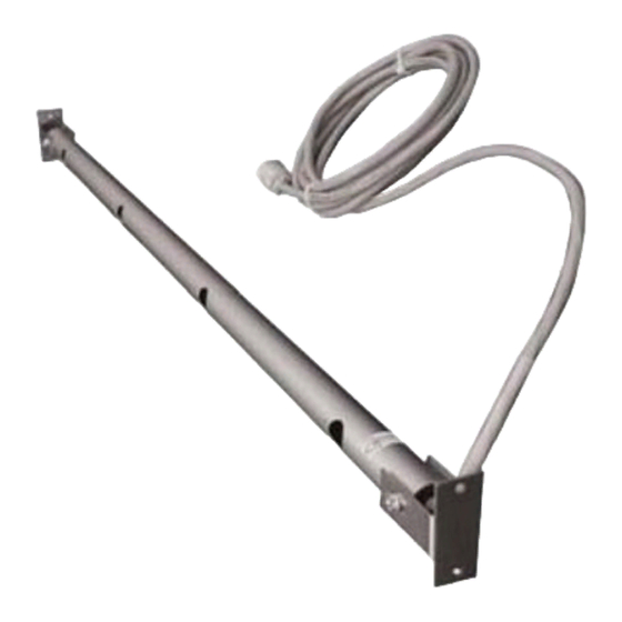
This document provides the instructions necessary
to install Internal Mount Probes as shown in Figure
1. Internally mounted probes are installed inside of
the duct/plenum. Internal mounting is ideal for
applications where access through the outside of
the duct is limited or not possible and is also well
suited for installation in air handling units and
plenums. Installation consists of marking the duct
for bracket installation and then securing the probe
mounting
brackets. For detailed probe information, refer to
the Duct/Plenum Probe technical manual under
separate cover. For detailed information on
transmitter set up and operation of the complete
airflow
measurement
associated transmitter technical manual under
separate cover. Observe the following installation
precautions:
Location of the probe(s) is critical for proper performance of the airflow station. Probes
must be installed in accordance with the engineer's plans and EBTRON Minimum
Placement Guidelines (Figures 4 and 5) for the specified location. For additional probe
placement detail, refer to the probe technical manual under separate cover.
Ensure that adequate installation/service clearance exists at the installation site to
permit installation of the probe into the duct/plenum, and that the cable length for the
probes is sufficient to reach the planned transmitter installation. Refer to the mechanical
details of Figure 2.
On applications where multiple probes are to be installed at a single measurement
location, install probes in accordance with Figure 3 (Internal Mount Probe
Spacing/Configuration). In addition, when traverse data is desired (Gold Series GP1
probes only), place the lowest numbered probe at the top of the duct for horizontal
mounting. For vertical mounting, place the lowest numbered probe on the left side of
duct when viewed from the upstream side of the mounting location, with cables exiting on
the higher side to prevent any potential moisture from accumulating on the heated
sensors.
Insulation that may interfere with mounting should be temporarily removed prior to
installation and replaced afterwards.
INTERNAL MOUNTING OVERVIEW
Figure 2 provides Standard Internal Mount probe installation details. Probes are installed from inside of
the duct or plenum using the included brackets. Internal insulation that may interfere with mounting
should be temporarily removed to permit installation. Internal mount probes are manufactured shorter to
permit 0.75 in (19 mm) adjustment and allow for installation clearance. Install each probe as follows
using the convenient check boxes at each step.
EBTRON, Inc. 1663 Hwy. 701 S., Loris SC 29569 • Toll Free: 800.2EBTRON (232.8766) • Fax: 843.756.1838 •
®
GP1/HP1/SP1 D
station,
refer
to
the
& P
UCT
LENEM
Figure 1. Internal Mount Probe
CAUTION
P
- I
M
ROBES
NTERNAL
Q
I
UICK
NSTALLATION
Document Number 930-0035
www.EBTRON.com
OUNT
G
UIDE
1
Advertisement
Table of Contents

Related Manuals for Ebtron GP1


Summary of Contents for Ebtron GP1
- Page 1 0.75 in (19 mm) adjustment and allow for installation clearance. Install each probe as follows using the convenient check boxes at each step. EBTRON, Inc. 1663 Hwy. 701 S., Loris SC 29569 • Toll Free: 800.2EBTRON (232.8766) • Fax: 843.756.1838 • www.EBTRON.com...
- Page 2 11. Mark the non cable end bracket installation locations for each probe on the opposite side of the inside duct wall. Proceed to step 12, Final Assembly. EBTRON, Inc. 1663 Hwy. 701 S., Loris SC 29569 • Toll Free: 800.2EBTRON (232.8766) • Fax: 843.756.1838 • www.EBTRON.com ...
- Page 3 Complete the installation, wiring and set up of the associated transmitter as detailed in the separate Transmitter Installation Guide and the Installation, Operation and Maintenance Technical Manual (each provided under separate cover). EBTRON, Inc. 1663 Hwy. 701 S., Loris SC 29569 • Toll Free: 800.2EBTRON (232.8766) • Fax: 843.756.1838 • www.EBTRON.com ...
- Page 4 Figure 2. Standard Insertion Mount Probe Mechanical Detail Figure 2. Standard Internal Mount Probe Mechanical Detail • • • EBTRON, Inc. 1663 Hwy. 701 S., Loris SC 29569 • Toll Free: 800.2EBTRON (232.8766) • Fax: 843.756.1838 • www.EBTRON.com ...
- Page 5 1/4 X 1/8 X 45° Figure 4. Insertion Mount Probe Spacing/ Configuration Figure 3. Internal Mount Probe Spacing/Configuration • • • EBTRON, Inc. 1663 Hwy. 701 S., Loris SC 29569 • Toll Free: 800.2EBTRON (232.8766) • Fax: 843.756.1838 • www.EBTRON.com ...
Need help?
Do you have a question about the GP1 and is the answer not in the manual?
Questions and answers