OilGear F1U Series Service Instructions Manual

Type “pvg” pumps

Advertisement

OILGEAR TYPE "PVG" PUMPS -
-048/-065/-075 (SERIES F1U)
PURPOSE OF INSTRUCTIONS
These instructions will simplify the installation,
operation, maintenance and troubleshooting of
Oilgear type "PVG" pumps.
REFERENCE MATERIAL
Fluid Recommendations .....................................................................................Bulletin 90000
Contamination Evaluation Guide.........................................................................Bulletin 90004
Filtration Recommendations ...............................................................................Bulletin 90007
Piping Information ...............................................................................................Bulletin 90011
Installation of Vertically Mounted Axial Piston Units ...........................................Bulletin 90014
PVG Open Loop Pumps, Sales........................................................................ Bulletin 47019-I
Pump Control Instructions, Series F1U
"P-1NN" Single Pressure Compensator ............................................................Bulletin 947651
"P-1NN/F" Single Pressure Compensator w/Load Sense .................................Bulletin 947652
"P-1NN/H" Single Pressure Compensator w/H.P. Limiter ....................................Bulletin 947653
"P-1NN/G" Horsepower Limiter w/Load Sense .................................................Bulletin 947654
"P-2" Dual Pressure Compensator....................................................................Bulletin 947655
"P-C" Single Pressure - Soft Start.....................................................................Bulletin 947656
"P-A" or "P-B" Electronic Pressure Compensator .......................Bulletins 947556 and 947657
"P-CNN/H" Single Pressure - Soft Start w/H.P. Limiter ...............Bulletins 947558 and 947658
"P-2NN/H" Dual Pressure Compensator w/H.P. Limiter ..............Bulletins 947559 and 947659
"V-S25" Electro Hydraulic Servo Valve..............................................................Bulletin 947560
"V-M20" Electro Hydraulic Servo Valve .............................................................Bulletin 947561
November 2009
Bulletin 947023
SERVICE INSTRUCTIONS
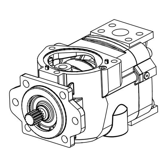
Figure 1. Typical Oilgear "PVG" Open Loop Pump
THE OILGEAR COMPANY
2300 South 51st Street
Milwaukee, Wisconsin 53219
THE OILGEAR COMPANY
OILG0457
Become familiar with the construction, principle of
operation and characteristics of your pump to help
you attain satisfactory performance, reduce shut-
down and increase the pump's service life. Some
pumps have been modified from those described in
this bulletin and other changes may be made
without notice.
www.oilgear.com
Bulletin 947023
1
Bulletin 947023

Advertisement

Table of Contents
loading

Summary of Contents for OilGear F1U Series

  • Page 1 OILGEAR TYPE “PVG” PUMPS - -048/-065/-075 (SERIES F1U) SERVICE INSTRUCTIONS OILG0457 Figure 1. Typical Oilgear “PVG” Open Loop Pump PURPOSE OF INSTRUCTIONS Become familiar with the construction, principle of operation and characteristics of your pump to help These instructions will simplify the installation,...
  • Page 2: Safety Symbols

    Or visit our website: www.oilgear.com. hydraulic leaks, please contact Oilgear Please contact us if you have any prior to servicing. questions regarding the information in this instruction bulletin. THE OILGEAR COMPANY © 2009 THE OILGEAR COMPANY - ALL RIGHTS RESERVED Bulletin 947023...
  • Page 3 Damaged or leaking pipes must be of the correct length and must comply be replaced before the system is returned with hose manufacturer’s to service. Please contact Oilgear if you Oilgear’s installation guidelines require assistance or have questions. recommendations.
  • Page 4 Serious injury adjustments. can result without proper protective gear. WARNING WARNING An Oilgear pump must not be modified in Make sure to keep hands and feet and without authorization from other parts of your body clear of revolving Oilgear.
  • Page 5: Preparation And Installation

    1 on the top side. Secure the pump to a rigid mounting POWER surface. Refer to the referenced Oilgear Piping Information Bulletin 90011. Power is required in proportion to volume and pressure used. Motor size recommendations for...
  • Page 6 The and Oilgear Contamination Evaluation Guide system can usually be filled by running the Bulletin 90004. Oilgear recommends use of a filter pump and operating the control. in the pressure or return line. Replace filter 5.
  • Page 7: Principle Of Operation

    B until its innermost stroke (D) is reached. At this point, the piston bore passes from the lower to the upper crescent again and the cycle is repeated. OIL_0001 Figure 3. Position B, Pump During Full Delivery from Port B THE OILGEAR COMPANY Bulletin 947023...
  • Page 8 OILG-0002 Figure 4. Position B/2, Pump During One Half Delivery from Port B NEUTRAL NEUTRAL OILG-0003 Figure 5. Position N, Pump in Neutral, No Stroke, No Delivery Refer to SPECIFICATIONS THE OILGEAR COMPANY Bulletin 947023...
  • Page 9: Specifications

    175,3 160,0 SAE “B” 2 bolt All dimensions (without controls) are approximate. For detailed dimensions, contact your Oilgear Representative. * Weight with P Control and rear port valve plate Table 2. Nominal Dimensions and Weights Without Controls Refer to installation drawings for more detailed dimensions and port configurations.
  • Page 10: Troubleshooting

    Worn or grooved cylinder barrel (101) and/or valve plate (401) mating surfaces. Inspect components. Replace. Faulty output circuit components (continuous blowing relief valves or "slip" through valves, cylinder or other components). Insufficient cooling provision or clogged coolers. Inspect for obstruction. THE OILGEAR COMPANY Bulletin 947023...
  • Page 11: Testing And Adjusting

    (siphon) the reservoir. Additional leakage indicates wear, but NOTE does not become critical until it impairs performance. THE OILGEAR COMPANY Bulletin 947023...
  • Page 12: Control Group

    1. Block the pump on a bench with the drive shaft facing down. 2. Remove the valve plate (401) by removing four cap screws (403) and lifting it straight up. 3. Remove valve plate O-ring (404) and (411). THE OILGEAR COMPANY Bulletin 947023...
  • Page 13: Rotating Group

    (102) and remove the fulcrum ball (103) maintaining the hydraulic system or the and shoe retainer spring (105). Oilgear pump. Wear correct protective gear, safety glasses, gloves and safety shoes. Serious injury can result without proper protective gear.
  • Page 14 Be sure to stone lightly. Any excessive NOTE stoning will remove the hardened surface. If wear or damage is extensive and defects cannot be removed, replace if necessary or if you suspect them of being bad. THE OILGEAR COMPANY Bulletin 947023...
  • Page 15 4. The swashblock is inserted from the valve plate end. Insert swashblock (201) into the pump housing. Once in place, be sure the swashblock swivels in the saddle bearings. With new bearings, swiveling may be stiff and not always smooth. THE OILGEAR COMPANY Bulletin 947023...
  • Page 16 (202) engagement. Continue pushing the cylinder forward until the piston shoes contact the swashblock; the back of the cylinder should be located approximately 0.4 inches (10,2 mm) outside the back of the pump housing. THE OILGEAR COMPANY Bulletin 947023...
  • Page 17 505 & 506 Depends on Adapter 505 Cover Plate 138-70 505 SAE A 153-70 505 SAE A-A 034-70 505 SAE B or B-B 158-70 506 SAE A 042-70 506 SAE B or B-B 155-70 Table 4. O-ring Sizes THE OILGEAR COMPANY Bulletin 947023...
  • Page 18: Parts List

    PVG -048/-065/-075 B-Frame Pump PARTS LIST Parts used in these assemblies are per Oilgear specifications. Use only Oilgear parts to ensure compatibility with assembly requirements. When ordering replacement parts, be sure to include pump type and serial number, bulletin number and item number.
  • Page 19 PARTS LIST drawings on pages 24 through 27. Parts are common between pumps. Only the differences are shown. Parts used in this assembly are per Oilgear specifications. Use only Oilgear parts to ensure the compatibility with the assembly requirements. When ordering replacement parts, be sure to include pump type and serial number, bulletin number and item number.
  • Page 20: Service Kits

    Rotating Group PVG-048/065 L517104-103 B2(A) 101, 102(9), 103, 104, 105 PVG-075 L517105-103 B2(A) Piston & Shoe Sub-Assembly PVG-048/065 K407905-R65 B2(A) 102(9) PVG-075 K407905-A75 B2(A) Shoe Retainer & Fulcrum Ball PVG-048/065 L319221-365 103, 104 PVG-075 L319221-375 THE OILGEAR COMPANY Bulletin 947023...
  • Page 21 401E, 403(4), 404, 405(2), 407(2), 408(2), 410(2), 411 Nitrile Seals L517105-409 EPR Seals L517105-412 PVG-075 Side Port, Thru-Shaft RH Viton Seals L517105-404 401F, 403(4), 404, 405(2), 406, 407, 408(2), 409, 410, 411 Nitrile Seals L517105-416 EPR Seals L517105-413 THE OILGEAR COMPANY Bulletin 947023...
  • Page 22 Viton Seals L250667-014 505, 506 Nitrile Seals L250667-013 EPR Seals L250667-015 SAE A-A Adapter Viton Seals L250667-019 505, 508 Nitrile Seals L250667-020 EPR Seals L250667-021 Shaft Seal Viton Seals 51155-5 Nitrile Seals 51155-7 EPR Seals L51155-3RP THE OILGEAR COMPANY Bulletin 947023...
  • Page 23 (B) F1 Pump case and Hydro bearing are not interchangeable with previous design series F1 Pump requires F1 Control Pump cases are interchangeable prior to F1 A1 series has #12 SAE threaded case drain connection B1 and B2 series have #16 SAE threaded case drain connection THE OILGEAR COMPANY Bulletin 947023...
  • Page 24 PVG -048/-065/-075 B-Frame Pump Figure 8. Cross Section and Exploded Parts Drawing for PVG 048, 065 and 075 (517105-200 sheet 1 of 7) THE OILGEAR COMPANY Bulletin 947023...
  • Page 25 PVG -048/-065/-075 B-Frame Pump Figure 9. Exploded Parts Drawing for PVG 048, 065 and 075 (517105-200 sheet 2 of 7) THE OILGEAR COMPANY Bulletin 947023...
  • Page 26 PVG -048/-065/-075 B-Frame Pump Figure 10. Cross Section Drawing for PVG 048, 065 and 075 (517105-200 sheet 6 of 7) THE OILGEAR COMPANY Bulletin 947023...
  • Page 27 PVG -048/-065/-075 B-Frame Pump Figure 11. Cross Section and Exploded Parts Drawing for PVG 048, 065 and 075 (517105-200 sheets 6 and 7 of 7) THE OILGEAR COMPANY Bulletin 947023...
  • Page 28: After Sales Services

    AFTER SALES SERVICES SERVICE SCHOOLS Oilgear conducts training to train your maintenance At Oilgear we build products to last. It is the nature personnel. “General” hydraulic electronic of this type of machinery to require proper training is conducted at our Milwaukee, Wisconsin maintenance regardless of the care we put into plant on a regular basis.

This manual is also suitable for:

Pvg 065Pvg 048Pvg 075

Table of Contents