Meyer Sound MPS-488HP Operating Instructions Manual
Hide thumbs
Also See for MPS-488HP:
- Operating instructions manual (56 pages) ,
- Operating instructions manual (32 pages)

Related Manuals for Meyer Sound MPS-488HP


Summary of Contents for Meyer Sound MPS-488HP
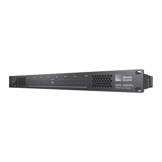
- Page 1 OPERATING INSTRUCTIONS POWER MPS-488HP Power Supply Keep these important operating instructions. Check www.meyersound.com for updates.
- Page 2 The contents of this manual are furnished for informational purposes only, are subject to change without notice, and should not be con- strued as a commitment by Meyer Sound Laboratories Inc. Meyer Sound assumes no responsibility or liability for any errors or inaccura- cies that may appear in this manual.
-
Page 3: Table Of Contents
CONTENTS Chapter 1: Introduction How to Use This Manual MPS-488HP External Power Supply Chapter 2: MPS-488HP Front and Rear Panels MPS-488HP Front Panel MPS-488HP Rear Panel MPS-488HP Current Draw Electrical Safety Guidelines Chapter 3: Powering Loudspeakers with the MPS-488HP Chapter 4: MPS-488HP RMS Option... -
Page 5: Chapter 1: Introduction
The MPS-488HP IntelligentDC power supply delivers power configuring a Meyer Sound MPS-488HP. In particular, pay and balanced audio to up to eight Meyer Sound loudspeak- close attention to material related to safety issues. ers that require an external DC power supply. - Page 6 DC power from the replaces the MPS-488 model, which was origi- nally designed for use with MM-4XP loudspeakers. MPS-488HP to the loudspeakers. Longer cable lengths are The MPS-488 is also compatible with larger Intelli- possible for moderate applications that don't drive the loud-...
-
Page 7: Chapter 2: Mps-488Hp Front And Rear Panels
MPS-488HP and inspect the loudspeaker cabling for that channel. AC Power Table 1 lists the possible states for the Voltage LEDs. The MPS-488HP is powered on and off with the AC Power switch. Table 1: Voltage LEDs State... -
Page 8: Mps-488Hp Rear Panel
MPS-488HP and inspect out the world. Make sure to use the correct power cable for the loudspeaker cabling the AC power in your area. The MPS-488HP operates at an for the channel AC voltage range of 100–240 V at 50–60 Hz. - Page 9 MPS-488HP OPERATING INSTRUCTIONS Link Switches Routing Two Inputs to Four Outputs Each To route two inputs to four channel outputs each: Link switches determine how inputs are routed to outputs. When an input’s Link switch is OFF (set to the down posi- ■...
- Page 10 1 channel output, 10 kOhm input impedance ■ MPS-488HP. If audio signal is present on both chan- nels connected to an HMS-15, the signal is summed 2 channel outputs, 5 kOhm input impedance ■...
-
Page 11: Mps-488Hp Current Draw
MPS-488HP OPERATING INSTRUCTIONS MPS-488HP CURRENT DRAW ELECTRICAL SAFETY GUIDELINES The current draw for the MPS-488HP and its connected Pay close attention to these important electrical and safety loudspeakers is dynamic and fluctuates as operating levels guidelines. change. Since different cables and circuit breakers heat up ■... - Page 12 CHAPTER 2: MPS-488HP FRONT AND REAR PANELS...
-
Page 13: Chapter 3: Powering Loudspeakers With The Mps-488Hp
2. Connect audio sources (from a mixer or processor) to the MPS-488HP channel inputs. Use balanced XLR cables. MPS-488HP 3. Use the MPS-488HP Link switches to route channel inputs to the desired channel outputs (see “Link Switches” on page 9). - Page 14 EN3 5-pin female cables. speaker cables, refer to Appendix B, “Assembling Loudspeaker Cables.” 5. Power on the MPS-488HP and monitor the LEDs on its front panel to verify the connections (see “Voltage and Load Current LEDs (1–8)” on page 7).
-
Page 15: Chapter 4: Mps-488Hp Rms Option
MPS-488HP (when equipped with the factory- installed RMS option). Up to eight IntelligentDC loudspeak- ers can be connected to the MPS-488HP with their voltage and DC current being monitored from Compass RMS soft- ware. Loudspeakers can also be muted and unmuted from the software. -
Page 16: Rms Module
RMS cables. The RMS blocks allow cables to be securely attached to the RMS ■ If the MPS-488HP has not yet been discovered on the module with screws. RMS network (Wink/Activity LED not lit), press the Iden- tify button to discover and enable it. -
Page 17: Discovering The Mps-488Hp
The MPS-488HP icon in the RMS program includes global Mute and Solo buttons at the bottom of the icon that affect all loudspeakers connected to the MPS-488HP, as well as a Wink button for identifying the power supply. The MPS-488HP icon also includes individual Mute buttons for each loudspeaker channel. - Page 18 CHAPTER 4: MPS-488HP RMS OPTION...
-
Page 19: Appendix A: Mps-488Hp Accessories
APPENDIX A: MPS-488HP ACCESSORIES PHOENIX AND EN3 LOUDSPEAKER CABLES The following Phoenix and EN3 cables are available from Meyer Sound and can be used to connect loudspeakers to MPS-488HP power supplies. NOTE: Phoenix and EN3 loudspeaker cables and bulk cable use Belden 1502R (regular) or Belden 1502P (plenum) cable. - Page 20 APPENDIX A: MPS-488HP ACCESSORIES PHOENIX AND EN3 CABLE CONNECTORS AND ADAPTERS The following cable connectors and adapters are available from Meyer Sound. Phoenix and EN3 Cable Connectors and Adapters Part Number Connector/Adapter 484.065 Phoenix 5-pin female cable mount connector Connects to MPS-488HP...
-
Page 21: Appendix B: Assembling Loudspeaker Cables
APPENDIX B: ASSEMBLING LOUDSPEAKER CABLES CAUTION: When wiring loudspeaker cables, it is extremely important that each pin be wired correctly. Make sure the 48 V DC from the external power supply is wired directly (and only) to the 48 V DC pins on the loud- speaker connector, and that the polarity is observed (negative to negative, positive to positive) to avoid damage to the loudspeaker. - Page 22 APPENDIX B: ASSEMBLING LOUDSPEAKER CABLES 3. Secure the conductors by tightening the five screws in the Phoenix cable mount connector. Screws should be torqued to 5–6 Nm (4.4–5.3 In-Lbs). CAUTION: Screws should not be inserted into the Phoenix connector while the connector rests in a mating plug.
- Page 23 MPS-488HP OPERATING INSTRUCTIONS 2. Insert the five exposed conductors into the five cable holes in a Phoenix 5-pin female cable mount connector. Use the following wiring scheme. Pin 5 White Audio signal (+) Pin 4 Blue Audio signal (-) Pin 3...
- Page 24 APPENDIX B: ASSEMBLING LOUDSPEAKER CABLES 6. Solder the five exposed conductors to the five pins on the EN3 cord connector using the following wiring scheme. Dimple identifies Pin 1 Pin 5, White, Pin 5, White, Pin 1, Black, audio (+) audio (+) 48 V DC (–) Pin 2, Red,...
- Page 25 MPS-488HP OPERATING INSTRUCTIONS To assemble an EN3-to-EN3 loudspeaker cable: 1. If the cable has not yet been stripped, strip one end of the cable. Strip the outer shielding by 1 inch and then strip the black, red, blue, and white wires by 0.275 inch.
- Page 26 APPENDIX B: ASSEMBLING LOUDSPEAKER CABLES 5. Repeat the previous steps to attach the EN3 5-pin female connector to the other end of the cable. Dimple identifies Pin 1 Pin 5, White, Pin 5, White, Pin 1, Black, audio (+) audio (+) 48 V DC (–) Pin 2, Red, Pin 4, Blue,...
- Page 27 MPS-488HP OPERATING INSTRUCTIONS 2. Insert the five exposed conductors into the five cable holes in a Phoenix 5-pin male cable mount connector. Use the fol- lowing wiring scheme. Pin 5 White Audio signal (+) Pin 4 Blue Audio signal (-)
- Page 28 APPENDIX B: ASSEMBLING LOUDSPEAKER CABLES 6. Fasten the five exposed conductors to the (1, 2, S, 5, and 6) pins on the ECO-M insert connector using the following wir- ing scheme. Pin 2, Red, Pin 1, Black, Pin 2, Red, 48 V DC (+) 48 V DC (–) 48 V DC (+)
-
Page 29: Appendix C: Mps-488Hp Specifications
APPENDIX C: MPS-488HP SPECIFICATIONS MPS-488HP Specifications FRONT PANEL LEDs Eight LEDs to indicate output voltage Eight LEDs to indicate load current REAR PANEL Audio Inputs Eight XLR 3-pin female connectors Link switches to route inputs to outputs Channel Outputs On MPS-488HP... - Page 30 APPENDIX C: MPS-488HP SPECIFICATIONS MPS-488HP Specifications Current Draw with Eight MM-10XP Subwoofers Idle 0.74 A rms (115 V AC); 0.54 A rms (230 V AC); 0.81 A rms (100 V AC) Maximum Long-Term Continuous 3.08 A rms (115 V AC); 1.49 A rms (230 V AC); 3.46 A rms (100 V AC) Burst 5.48 A rms (115 V AC);...
- Page 31 MPS-488HP OPERATING INSTRUCTIONS MPS-488HP DIMENSIONS 19.00 [483 mm] 14.10 [358 mm] 1.73 [44 mm] 16.90 [429 mm] 13.57 [345 mm] MPS-488HP Dimensions...
- Page 32 APPENDIX C: MPS-488HP SPECIFICATIONS MPS-488HP DIMENSIONS 19.00 [483 mm] 14.33 [364 mm] 1.73 [44 mm] 16.90 [429 mm] 13.57 [345 mm] MPS-488HP Dimensions...
- Page 36 Meyer Sound Laboratories Inc. © 2011, 2018 2832 San Pablo Avenue Meyer Sound. All rights reserved. Berkeley, CA 94702 MPS-488HP Operating Instructions +1 510 486.1166 PN 05.205.005.01 C www.meyersound.com...
Need help?
Do you have a question about the MPS-488HP and is the answer not in the manual?
Questions and answers