Table of Contents
Advertisement
Quick Links
Advertisement
Table of Contents

Related Manuals for Deca MIG Series


Summary of Contents for Deca MIG Series
- Page 1 Instruction manual 950686-00 22/09/18...
- Page 2 Fig.1 Fig.2 TYPE: xxxxxxxxxxxxxxx Xxxxxxxxxxxxxx SN: xxxxxxxxxxxxxxx EN 60 974 / 1 xx A/xx V - xxx A/xx V (max xxxA/xxV) xxx% xxxA xxxA Xx,x-xx,x xx x , V xx,xV xx,xV U1= xxxV I1max= x,xA I1eff= x,xA x ~ xx/xxHz IP 21 Fig.5 220 V 230 V 240 V...
- Page 3 (EN) KEY TO DANGER, MANDATORY AND PROHIBITION SIGNS Fig.8 DANGER STRONG MAGNETIC GENERAL DANGER FIELD DANGER OF ELECTRIC SHOCK DANGER OF BURNS DANGER OF WELDING FUMES PROTECTIVE BREATHING APPARATUS MUST BE WORN DANGER OF ULTRA VIOLET RADIATION PROTEPROTECTIVE MASKS MUST BE WORN DANGER BURNING...
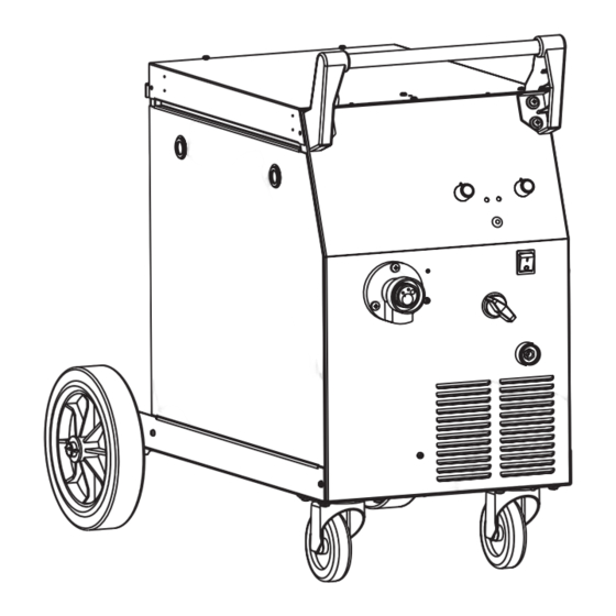
- Page 4 Main parts Fig. 1 Installing the protective gas cylinder** and pressure reducer** A) Spool compartment access door B) Spool holder reel C) Wire feeder D) Power cable „ Place the protective gas cylinder in an upright position, far away from the welding area. E) Gas hose connection Use the welding machine support or some other fixed part so that there is no risk of it F) ON/OFF switch...
Need help?
Do you have a question about the MIG Series and is the answer not in the manual?
Questions and answers