
Related Manuals for BLH NOBEL G5


Summary of Contents for BLH NOBEL G5
- Page 1 G5 Weighing Instrument Program version 1.3.X Fieldbus Option Manual PM and RM types...
-
Page 3: Table Of Contents
CONTENTS 1. Introduction ........1-1 General ..........1-1 Module installation ......1-1 Ordering information ......1-2 2. Modules ........2-1 Profibus-DP Module ......2-1 DeviceNet Module ....... 2-3 ControlNet Module ......2-5 EtherNet/IP Module ......2-6 3. Set-up ........... 3-1 General .......... -
Page 4: Intended Use
INTENDED USE The G5 Instrument family are measuring and control devices intended for industrial systems. Its basic function is to convert the signals from transducers to useful information. Transducer excitation is included as well as parameter controlled signal processing, indication of output levels, error supervision and operation of optional external equipment. -
Page 5: Introduction
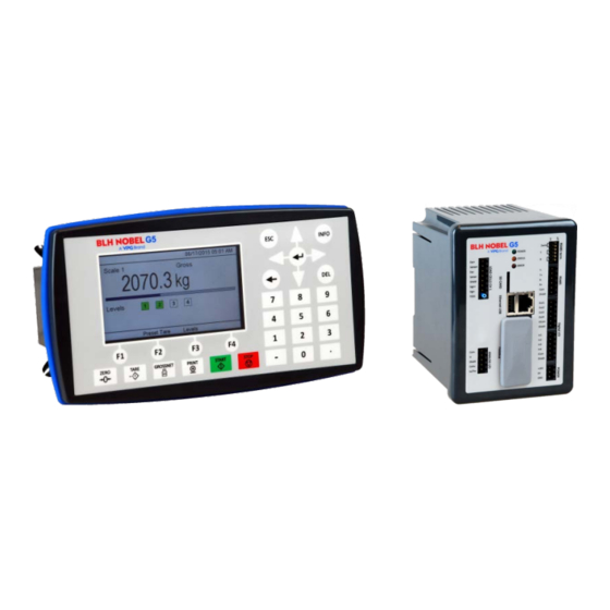
G5 Weighing Instrument 1. Introduction General The G5 Instruments are high performance single-channel weight indicators (PM model, panel mounted) or weight transmitters (RM model, DIN rail mounted) intended for industrial systems. This manual describes the functionality of the optional Fieldbus interface of the G5 Instrument. -
Page 6: Ordering Information
Technical Manual Ordering information If an (optional) fieldbus module is needed it must be ordered together with the instrument. Ordering numbers are shown below. If multiple instruments and/or fieldbus modules are purchased in the same order it must be clearly specified which module should be mounted in which instrument. -
Page 7: Modules
G5 Weighing Instrument 2. Modules Profibus-DP Module Profibus module front view (1) Operation mode LED. (2) Status LED. (3) Profibus connector. PROFIBUS DP-V1 Operation mode LED State Indication Not online / No power Green On-line, data exchange Flashing Green On-line, clear... - Page 8 For reliable fieldbus function, line termination must be arranged in both ends of the transmission line. For a G5 instrument, at the end of the cable, a connector with line termination should be used. For all other G5 Instruments, connection without line termination should be used.
-
Page 9: Devicenet Module
G5 Weighing Instrument DeviceNet Module DeviceNet module front view (1) Network Status LED. (2) Module Status LED. (3) DeviceNet connector. DeviceNet (Pin 1) Network Status LED State Indication Not online / No power Green On-line, one or more connections are established... - Page 10 For reliable fieldbus function, line termination must be arranged in both ends of the transmission line. For a G5 Instrument placed at the end of the line, terminate line by placing a 121-ohm resistor between CAN L (pin 2) and CAN H (pin 4).
-
Page 11: Controlnet Module
G5 Weighing Instrument ControlNet Module ControlNet module front view (1) Network Status LED A. (2) Module Status LED. (3) Network Status LED B. (4) ControlNet connector A. ControlNet (5) ControlNet connector B. Network Status LED A/B State Indication LED A and B Off... -
Page 12: Ethernet/Ip Module
Technical Manual EtherNet/IP Module ControlNet module front view (1) Network Status LED. (2) Module Status LED. (3) Link/Activity Port 1. (4) Link/Activity Port 2. EtherNet/IP Network Status LED LED State Indication No power or no IP address Green Online, one or more connections established (CIP class 1 or 3) Green, flashing Online, no connections established Duplicate IP address, fatal error... -
Page 13: Set-Up
3. Set-up General All operating functions in the G5 Instrument are controlled by parameters. The parameter values are permanently stored in the instrument and will not be lost when the unit is switched off. At delivery the parameters are factory-set to default values, giving the instrument an initial standard function. - Page 14 Fieldbus Manual Range/Alternatives Explanation and <default value> result of alternatives. DeviceNet, Address Range 0 - 63 DeviceNet address setting < 63 > Note: This parameter is only shown if parameter Fieldbus (in Hardware Configuration menu) is set to DeviceNet. ControlNet, Address Range 1 - 99 ControlNet address setting <...
-
Page 15: Output Data
G5 Weighing Instrument 4. Output Data Output data mapping is shown in the table below. Output data is 8 bytes as described in table below. Data direction is from network (PLC) to G5 Instrument. Byte Size Description 0 – 1 Command 2 –... -
Page 16: Commands
Fieldbus Manual Commands Cmd # Command Name Description No action When the same command is repeated the no action should be sent between the commands to make it possible for the instrument to detect new commands. Start operation When the instrument is in ‘Wait for start state’, this command can be used to start up the instrument. -
Page 17: Input Data
G5 Weighing Instrument 5. Input Data Byte Size Description Note Instrument error Instrument Status Instrument State Command acknowledge Command error Level status Setpoint status Input and Output status 8 – 9 Error code 10 – 11 Scale status 12 – 15... -
Page 18: Instrument Error
Note 7: Analog input value always with 3 decimals. Note 8: The value is in integer format, i.e. it does not have any decimals. Note 9: These bytes are not used in the standard version of the G5 software. The content is always 0. -
Page 19: Instrument State
G5 Weighing Instrument Instrument state This register contains the state of the G5 instrument. Code Description ‘Starting up’ state. The instrument is starting up after a reset or power on. ‘Wait for start’ state. The instrument is waiting for a start command to go in process. -
Page 20: Setpoint Status
Fieldbus Manual Setpoint status 1-4 Bits in this byte have the following meaning: Bit no Function Comment Setpoint 1 activated See description for setpoint function. Setpoint 1 cycle done -“- Setpoint 2 activated -“- Setpoint 2 cycle done -“- Setpoint 3 activated -“- Setpoint 3 cycle done -“-... -
Page 21: Scale Status
G5 Weighing Instrument Scale Status Bits set to 1 in this register have the following meaning: Bit no Function Comment Not used Not used in the fieldbus interface Not used Not used in the fieldbus interface Not used Not used in the fieldbus interface Good zero (disp. -
Page 22: Flow Rate
Fieldbus Manual Flow rate The flow rate value consists of 4 bytes. The weight should not be read alone because the status and error codes are stored in other registers. The flow rate is only valid when the register ‘Scale Error code’ equals 00. Flow rate can be in integer format or floating point format depending on the setting. -
Page 23: Number Format
G5 Weighing Instrument Clock These bytes are used to read the time and date from the instrument. Year is given in 2 bytes while month (1 – 12), day (1 – 31), hour (0 – 23), minute (0 – 59) and second (0 – 59) is one byte each. - Page 24 Fieldbus Manual Example 2: Setting ‘Setpoint 4 value’ to 123.5. Here we are assuming that the setpoint has 3 decimals. 1. Make sure that the previous command was not 222. Set command to 0 if previous command was 222. 2. Set parameter ID to 4 (bytes 2 - 3). 3.
-
Page 25: Fieldbus Interface
G5 Weighing Instrument 6. Fieldbus interface The optional fieldbus interface is based on a network communication module from HMS Industrial Networks. Available fieldbuses are Profibus, DeviceNet, ControlNet and EtherNet/IP. With setup parameters the fieldbus interface is configured for the specific needs of an installation. -
Page 26: Ethernet/Ip
Fieldbus Manual EtherNet/IP Use the EDS file provided when installing the G5 in a system. EDS file name is 005A0000002E0100.eds. After installing the EDS file in the development system of the PLC, create a G5 in the PLC system. In the Select Module Type pop-up window select HMS Industrial Networks AB in the Vendor filter and choose the ABCC module (Anybus-CC EtherNet/IP 2-Port). -
Page 27: Profibus Dp-V1
Use the provided GDS file VISH0F83 with revision 2. This revision is intended for G5 with SW revision 1.3.0 or later. Revision 1 of the GDS file is used with G5 with SW revision 1.0.0, 1.2.0 or 2.0.1 but cannot be used with 1.3.0 that is described in this manual. - Page 28 Fieldbus Manual...
-
Page 29: Maintenance
G5 Weighing Instrument 7. Maintenance General This chapter describes the maintenance functions when handled from the local display. The Maintenance menu includes a number functions used for diagnostics, maintenance and program upgrade purposes. The Maintenance menu is found under the Main menu. - Page 32 Document no. 35234 Publication no. 601 364 R0 © Vishay Nobel AB, 2017-04-12 Subject to changes without notice. Web site: www.blhnobel.com...
Need help?
Do you have a question about the G5 and is the answer not in the manual?
Questions and answers