Table of Contents
Advertisement
Advertisement
Table of Contents

Subscribe to Our Youtube Channel
Related Manuals for BLH NOBEL G5-PM-S-DC-W


Summary of Contents for BLH NOBEL G5-PM-S-DC-W
- Page 1 G5 Weighing Instrument Program version 1.4.X Technical Manual PM and RM types...
-
Page 3: Table Of Contents
Serial interface ........6-1 CONTENTS Modbus RTU Slave ......6-1 Modbus TCP Slave ......6-2 1. Introduction ........1-1 Ftp Server ........... 6-3 General ..........1-1 Fieldbus interface ........ 6-3 Maintenance ........1-2 Modbus protocol ........6-3 Safety information ....... 1-2 7. - Page 4 Technical Manual PRECAUTIONS READ this manual BEFORE operating or servicing this instrument. FOLLOW these instructions carefully. SAVE this manual for future reference. WARNING Only permit qualified personnel to install and service this instrument. Exercise care when making checks, tests and adjustments that must be made with power on.
-
Page 5: Introduction
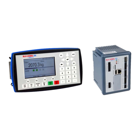
G5 Weighing Instrument 1. Introduction General The G5 Instruments are high performance single-channel weight indicators (PM model, panel mounted) or weight transmitters (RM model, DIN rail mounted) intended for industrial systems. The basic function is to convert the signals from strain gauge transducers to useful weight information. -
Page 6: Maintenance
Technical Manual Modbus RTU protocol is used for the serial interfaces and Modbus TCP for the Ethernet connection. Optional fieldbus interface for Profibus, DeviceNet, ControlNet, EtherNet/IP or PROFINET can be used. The serial port can also be used to connect a printer for printing of weight or for showing weight on an external display unit. -
Page 7: Technical Data
G5 Weighing Instrument Technical data Enclosure PM - Panel mount RM – DIN-rail mount types Enclosure Plastic, PC Plastic, PC design Dimensions WxHxD 226x126x100 mm WxHxD 95x130x93 mm (8.9”x5.0”x3.9”) (3.7”x5.1”x3.7”) Depth behind front 100 mm (3.9”) Depth above DIN-rail 93 mm (3.7”) Front panel depth 14 mm (0.55”) Depth not including connectors, screw terminals or cables... - Page 8 Technical Manual Fieldbus For process data and control (optional) Types Profibus, DeviceNet, ControlNet, EtherNet/IP or PROFINET Version 2.0, FAT 32 file format USB Memory USB type for PC For backup and restore of set-up parameters. Operational insulation, max 500mA output. SD-Card Micro SD, Micro SDHC types.
- Page 9 G5 Weighing Instrument Analog output Resolution 65000 units, 16 bits Voltage output 0 – 10 V, -10 – 10 V, > 1 kohm load Current output 4 – 20 mA, 0 – 20 mA, -12 – 20 mA, -20 – 20 mA, <...
-
Page 10: Ordering Information
Technical Manual Ordering information PM model, single channel weighing, 24VDC supply Denomination: G5-PM-S-DC-W P/N: 110767 (ordering number). PM model, single channel weighing, 110/230VAC supply Denomination: G5-PM-S-AC-W P/N: 110768 (ordering number). RM model, single channel weighing, 24VDC supply Denomination: G5-RM-S-DC-W P/N: 110771 (ordering number). -
Page 11: Installation
G5 Weighing Instrument 2. Installation Mechanical installation See chapter Introduction – Technical data for references to PM and RM mechanical measures: outer extents and body extents. The safety of any system incorporating the equipment is the responsibility of the integrator of the system. Allow at least 20 mm free space around the instrument for ventilation. - Page 12 Technical Manual RM type instrument: The unit snaps on to a DIN-rail. Place the unit with the front slightly tilted upwards on to the DIN-rail. Make sure the hooks at the rear of the instrument enclosure are gripping over the upper edge of the DIN rail. Push the unit down and towards the DIN-rail until it snaps into locked position.
-
Page 13: Electrical Installation
IEC 60947-1 and IEC 60947-3. The power supply for the instruments can be an external DC source for G5-PM-S-DC-W and G5-RM-S-DC-W units or external AC mains for G5-PM-S-AC-W units. For electrical installation with DC supply, see section DC Supply. - Page 14 Technical Manual The following applies to HW version 2 or later. See the System Information menu to find out the actual HW version of the instrument. The shield of the load cell cable can also be connected at terminal 26 to achieve best possible noise immunity of the LC input.
- Page 15 G5 Weighing Instrument Field Bus Slot for optional Fieldbus interface. Profibus DP-V1, DeviceNet, ControlNet, EtherNet/IP and PROFINET are available. See separate Fieldbus option manual P/N 601402 for details. The USB connector is intended for USB memory only. This port has operational insulation (from HW version 2).
- Page 16 Ex zener barriers. Shield can be connected to terminal 26 if the instrument is of HW version 2 or later. In the junction box SL-4 from BLH Nobel all necessary terminals and interconnections are provided.
- Page 17 G5 Weighing Instrument Solid state relay outputs Digital outputs use terminals 7 to 10 with terminal 11 (OCom) as the common connection. Four digital outputs are provided with contact rating given in Technical data. Output functionality is set-up in the G5. External 24 VDC power supply must be used.
-
Page 18: Front Panel
Technical Manual Front panel Display At normal operation the instrument displays weight value(s) and, in some cases, the gross weight as a graphic bar. Together with the weight value additional information such as preset tare, status for the level supervision can also be displayed. This is configured with parameters. - Page 19 G5 Weighing Instrument Name Function ZERO Setting the gross weight value to zero (provided the value is in the zeroing range: -1 % to +3 % of the capacity) and setting the auto tare value to zero. TARE Taring, i.e. entry of the gross weight as auto tare value and display of net weight zero.
- Page 20 Technical Manual 2-10...
-
Page 21: Set-Up
G5 Weighing Instrument 3. Set-up General All operating functions in the G5 Instrument are controlled by parameters. The parameter values are permanently stored in the instrument and will not be lost when the unit is switched off. At delivery the parameters are factory-set to default values, giving the instrument an initial standard function. -
Page 22: Connecting A Pc To The Instrument
Technical Manual Digital Outputs: The digital outputs menu contains the settings controlling the function of each output. Each output can be assigned an output function: Level output status, setpoint output status, net mode, good zero, stable weight displayed or In Process status. - Page 23 G5 Weighing Instrument Navigating in a menu is done with arrow Main Menu 10/02/2015 01:28 PM keys. To open a sub menu, e.g. Parameter Set-up, select the desired line Levels Setpoints with arrow keys (selected sub menu is Preset Tare highlighted) and press Enter.
-
Page 24: Menu Structure
Technical Manual Menu structure Main Menu General Operational Data Menus Miscelaneous Levels parameters for Setpoints instrument set-up Levels Preset Tare Accumulated Weights Level values for Clock Set-up configured levels Parameter Set-up Menus Hardware Config. Parameter Set-up System Information Fieldbus selection Maintenance Network Configuration Setpoints... -
Page 25: Parameters
G5 Weighing Instrument Parameters On the following pages a survey of all parameters is presented. The parameters are divided in groups following the menu they belong to. For choice parameters the available choices are given. For numerical parameters, a value range is given. At the end of the table, the default value is given in <... - Page 26 Technical Manual Range/Alternatives Explanation and <default value> result of alternatives. Info Line 2 Mode Not in use Defines the mode of the first information line on the 1 scale Acc. Weight screen on the graphical display. Preset Tare Not in use: Info line 2 is not used. Auto Tare Accumulated Weight: The accumulated weight is shown on <...
- Page 27 G5 Weighing Instrument Range/Alternatives Explanation and <default value> result of alternatives. Operator Code Range: Defines the valid code for Operator lock. If ‘Set-up lock’ (see 1 - 9999 below) is ‘On’ this code will not give access to ‘Parameter Set- <1937>...
- Page 28 Technical Manual Range/Alternatives Explanation and <default value> result of alternatives. Menu Hardware config. Fieldbus Not In Use This parameter defines what type of fieldbus that will be used in Profibus the CPU. DeviceNet Not In Use: The fieldbus is not used regardless of any installed ControlNet module.
- Page 29 G5 Weighing Instrument Range/Alternatives Explanation and <default value> result of alternatives. Resolution 0.001 Defines the decimal point position and resolution format for the 0.002 displayed value. All set-up parameters using the measurement 0.005 unit will be written with the decimal point position selected in this 0.01 menu.
- Page 30 Technical Manual Range/Alternatives Explanation and <default value> result of alternatives. Motion Detect Window Range: Motion status is ‘on’ when the weight value is not stable. It goes 0 to 999999 off when the weight has been stable for the ‘No motion delay Unit: time’.
- Page 31 G5 Weighing Instrument Range/Alternatives Explanation and <default value> result of alternatives. Zero Tracking With this parameter automatic zero-tracking can be selected, or a combination of automatic zero-tracking and automatic zero On+AutoZero setting. <Off> Off: No zero tracking. On: Zero tracking active. On+AutoZero: Zero tracking and auto zeroing active.
- Page 32 Technical Manual Range/Alternatives Explanation and <default value> result of alternatives. Flow Rate Unit Unit/s Defines the engineering unit that should be used for the flow rate Unit/min value and for related set-up parameters. Unit/h If the flow rate unit exceeds 4 characters then it will be Unit*1000/m represented as ”/s”, ”/min”,”/h”, ”*/mi”...
- Page 33 G5 Weighing Instrument Range/Alternatives Explanation and <default value> result of alternatives. Exc. high curr. limit Range: An error is set if the actual excitation current exceeds the high 10 – 200 current limit. The value is automatically set to actual current Unit: mA +15mA when supervision is turned on.
- Page 34 Technical Manual Range/Alternatives Explanation and <default value> result of alternatives. Rated Output 1 Range: Defines the rated output signal for transducer 1. The value is 0 to 9.99999 specified in the transducer data sheet for transducer 1. If the Unit: mV/V total number of transducers and fixed supports is over 4: add up <2.03900>...
- Page 35 G5 Weighing Instrument Range/Alternatives Explanation and <default value> result of alternatives. Deadweight calibration related parameters Used when the scale is calibrated with weights. The instrument automatically reads the corresponding transducer signals. No of Calibration Points Range: Number of calibration points. 2 to 6 <2>...
- Page 36 Technical Manual Range/Alternatives Explanation and <default value> result of alternatives. Transd. Signal P1 Range: +/–9.99999 In this parameter, the transducer signal in the lowest calibration Unit: mV/V point is displayed, but the value cannot be edited. <0.00000> Transd. Signal P2 Range: +/–9.99999 In this parameter, the transducer signal in the second calibration Unit: mV/V...
- Page 37 G5 Weighing Instrument Range/Alternatives Explanation and <default value> result of alternatives. Table calibration related parameters Used when the scale is calibrated with recorded values from a previous calibration, normally a deadweight calibration. No of Calibration Points Range: Number of calibration points. 2 to 6 <2>...
- Page 38 Technical Manual Range/Alternatives Explanation and <default value> result of alternatives. Transd. Signal P1 Range: +/–9.99999 In this parameter, enter the recorded value for the transducer Unit: mV/V signal in the first calibration point. <0.00000> Transd. Signal P2 Range: +/–9.99999 In this parameter, enter the recorded value for the transducer Unit: mV/V signal in the second calibration point.
- Page 39 G5 Weighing Instrument Range/Alternatives Explanation and <default value> result of alternatives. Menu Serial Communication Serial Com. Mode Not in use Defines use of serial port. Modbus Slave Not in use: The port is not used. Printer Modbus Slave: The port is used for control unit communication. External Display Printer: The port is used for a printer.
- Page 40 Technical Manual Range/Alternatives Explanation and <default value> result of alternatives. Floating Point Format IEEE Sets how the Modbus slave should handle floating point values. Modicon Float IEEE: IEEE 32 bit floating point format < IEEE > Modicon Float: Modicon floating point format. See chapter ‘Communication’...
- Page 41 G5 Weighing Instrument Range/Alternatives Explanation and <default value> result of alternatives. Linefeeds Specifies the number of linefeeds (empty lines) that should be output after each printout. Note that if all 8 print positions above are set to Not in use no printout and no linefeeds will be printed.
- Page 42 Technical Manual Range/Alternatives Explanation and <default value> result of alternatives. Ext. Display 2 Mode For details see Ext. Display 1 Mode. Defines what data is shown on external display 2. Note: This parameter is only shown if External Display is selected in Serial Com.
- Page 43 G5 Weighing Instrument Range/Alternatives Explanation and <default value> result of alternatives. Menu ‘Modbus TCP Slave’ Modbus TCP Slave Enables/disables the Modbus TCP Slave. On: Modbus TCP Slave enabled. <Off> Off: Modbus TCP Slave disabled. Floating Point Format Modicon Sets how the Modbus TCP Slave should handle floating point IEEE values.
- Page 44 Technical Manual Range/Alternatives Explanation and <default value> result of alternatives. Menus Level Supervision NOTE: There are 4 levels each with the following four parameters described below. Level 1 Source ( - Level 4 Source) Not in use Defines the signal to be supervised by the level. Net Weight Not in use: The level is not used, any outputs set to work with Gross Weight...
- Page 45 G5 Weighing Instrument Range/Alternatives Explanation and <default value> result of alternatives. Menus Digital Inputs NOTE: There are 4 digital inputs each with the parameter described below. Digital Input 1 Use (- Input 4 Use) Not in use Defines the use of the internal digital inputs in the instrument. Tare Not in use: The input is not used.
- Page 46 Technical Manual Range/Alternatives Explanation and <default value> result of alternatives. Menu Analog Outputs Analog Out Source Not in use Defines the value to represent on analog output. Gross Weight Not in use: The analog output is not used. Net Weight Gross Weight: The output represents gross weight.
- Page 47 G5 Weighing Instrument Range/Alternatives Explanation and <default value> result of alternatives. Analog Out Range Low Range: Defines the weight that should give the lowest output (0 V / 0 mA +/–999999 / 4 mA) at this Analog output. Unit: Note: this parameter is not shown if parameter Measurem.
- Page 48 Technical Manual 3-28...
-
Page 49: Calibration
It is recommended to start with a data sheet calibration, which is easy to perform and gives a fairly good accuracy so the installation can be tested. Each transducer from BLH Nobel is delivered with a detailed data and calibration sheet. -
Page 50: Common Parameters
Technical Manual If the weight indicator must be replaced, a table calibration of the replacement unit can be performed, with recorded values from an earlier calibration. To get the best accuracy, a deadweight calibration with known weights to at least 2/3 of the measuring capacity, should be performed. - Page 51 G5 Weighing Instrument Number of scale divisions The number of scale divisions (div.) for a scale = ‘Capacity’ / ‘Resolution’. To get correct and stable weight display, parameter ‘Resolution’ should be set so that the number of scale divisions with the selected ‘Capacity’ is less than 6 000 (10 000). The number of scale divisions is also limited by the performance of the transducers and by how large a portion of the transducer capacity that is actually utilized.
-
Page 52: Data Sheet Calibration
Technical Manual Data sheet calibration Data sheet calibration is recommended as first-time calibration for a new installation. In data sheet calibration, values from the transducer data sheets are entered as parameter values, the scale need not be loaded and an accuracy of 0.1 % can be obtained. -
Page 53: Deadweight Calibration
G5 Weighing Instrument Table calibration Table calibration can be used to copy recorded values from a previous deadweight calibration of the weighing equipment into a replacement instrument. This is performed by entry of recorded weight values and corresponding transducer signal values into the instrument. - Page 54 Technical Manual Value Cal. P2, Value Cal. P3 etc. The scale should be loaded with known weights. These parameters show the load according to the previous calibration and the parameter values should be changed to the value of the known weights. As a parameter value is stored, the instrument will also store the corresponding transducer signal value for that calibration point.
-
Page 55: Operation
G5 Weighing Instrument 5. Operation General G5 instrument with strain gauge transducers is designed mainly for weighing and batching purposes. The measurement values are displayed at the front panel, and can also be transmitted to a master computer/PLC. A measurement values can also be presented as an analog output signal. Some functions in the instrument can be controlled by digital input signals, and digital outputs from the instrument can be used to indicate actual status of instrument, scale, levels and so on. -
Page 56: Display At Normal Operation
Technical Manual Display at normal operation On the weight display scale weight information is shown. Dedicated keys on the front panel are used to zero and tare the scale, to toggle between gross and net weight display and to print weighing results. If a name has been entered in parameter Scale Name it will be shown in the weight display screen. -
Page 57: Security Locks
G5 Weighing Instrument Security locks In the G5 instrument two security locks are included to prevent unauthorized access to the instrument via the panel keys. The locks can be activated by parameters in menu ‘Main menu/Parameter set-up/General’. The following requires a login password if the corresponding lock is on. Changing instrument clock: Operator lock. -
Page 58: Taring
Technical Manual Taring Taring means storing of a tare value and that the G5 instrument switches over to display of net weight. Net weight is equal to gross weight minus tare value. In the instrument two tare values can be stored, Auto tare and Preset tare. ‘Auto’... -
Page 59: Gross/Net Operation
G5 Weighing Instrument Gross/Net operation At normal operation the G5 instrument presents a numerical weight value at the display, either gross weight or net weight. When net weight is displayed the text ‘Net’ is shown on screen. Toggling between display of gross weight and net weight can be performed by pressing the GROSS/NET key. -
Page 60: Zero-Tracking/Automatic Zero Setting
Technical Manual Zero-tracking/Automatic zero setting In the instrument the functions zero-tracking and automatic zero setting can be enabled. Zero-tracking gives a continuous zero setting by slow changes in zero weight. The automatic zero setting performs zeroing of small negative gross weights. For both functions the following requirements should be met: •... -
Page 61: Load Cell Supervision
G5 Weighing Instrument Load cell Supervision The load cell input is supervised by the instrument. If a value is outside limits an error will be set. The following values are supervised: Value and error Description Error code type Excitation current Excitation is turned off. -
Page 62: Weight Printing
Technical Manual Weight printing General A printer can be used to print the displayed weight. The printer must be connected to the G5 Instrument serial communication port and the communication parameters must be correctly set. For details on printing function and set-up see chapters ‘Communication’... - Page 63 G5 Weighing Instrument Setup of printer Serial Com. Mode: Set to ‘Printer’ to activate the printing function in the G5 Instrument. Baudrate: As selected on the printer. Data Format: As selected on the printer. Print Position 1 - 8: A print out consists of up to 8 fields with configurable information.
-
Page 64: Main Menu
Technical Manual Main Menu Main Menu 10/02/2015 01:28 PM To reach the Main Menu, press Levels Setpoints the INFO button on the Preset Tare instrument front panel. Note that Accumulated Weights the INFO button is only functional Batched Weights from the weight display. Clock Set-up Parameter Set-up Navigating in a menu is done with... - Page 65 G5 Weighing Instrument Maintenance: Includes a number of functions for maintenance purposes. The available functions are Diagnostics, File Handling, Create Backup, Restore Backup, Set Default Values and Program Upgrade. See chapter ‘Maintenance’ for a detailed description of the functions. Network Configuration: The Network Configuration menu consists of the IP Configuration, Server Configuration and EtherNet/IP IP Configuration menus.
-
Page 66: Level Supervision
Technical Manual Level supervision The G5 instrument contains 4 supervision Levels that can be used to supervise defined signals in the instrument. The 4 digital outputs can be assigned as outputs for Levels. For each Level, supervised scale, hysteresis and operation mode for the digital output is controlled by set-up parameters. -
Page 67: Setpoint Function
G5 Weighing Instrument Setpoint function General The 4 Setpoints can be used for fast, accurate and reliable supervision of weight values. The Setpoint function is of a one shot type. The function is activated by a command from the master computer/PLC and deactivated when the weight has reached the Setpoint value. -
Page 68: Filter Function
Technical Manual Filter function In the instrument the weight value is filtered to produce a stable measurement. To allow adaptation to the dynamic requirements of the specific installation it is possible to select the filter bandwidth within a broad range. The lowest bandwidth is 0.125 Hz and the highest is 50 Hz. -
Page 69: Flow Rate
G5 Weighing Instrument Flow rate General The G5 instrument calculates the flow by measuring the weight change during a selected integration time and dividing by the time. The flow rate can be displayed as weight change per second, per minute or per hour. It will display weight or flow value, and switch over between weight and flow is accomplished with the function key 'W/F' or ‘F1’. - Page 70 Technical Manual Setting of flow rate unit Parameter Flow Rate Unit defines the engineering unit that should be used for the flow rate value and for related set-up parameters. If the flow rate unit exceeds 4 characters then it will be represented as ”/s”, ”/min”,”/h”, ”*/mi”...
- Page 71 G5 Weighing Instrument Hints and examples First of all it is important to have a good weighing application where you use the load cells in a good way to get high resolution and accuracy. It is possible to use low Bandwidth in the instrument to get a higher resolution and accuracy.
- Page 72 Technical Manual 5-18...
-
Page 73: Communication
G5 Weighing Instrument 6. Communication General The G5 Instrument has one serial communication port, one Ethernet port and an optional fieldbus module. The serial communication port can be used for communication with a control unit, for connecting a printer or for displaying the weight on an external display. The Ethernet port can be used for communication with a control unit and for file transfer to and from an external computer, using ftp (File Transfer Protocol). -
Page 74: Modbus Tcp Slave
Technical Manual Setup of Modbus RTU communication • The instrument will as default have the address 1. If more than one instrument is used in a network, each instrument must be given a unique address in parameter ‘Modbus RTU address’ (in ‘Parameter set-up’, menu ‘Communication’, sub menu ‘Serial Communication’). -
Page 75: Ftp Server
G5 Weighing Instrument Ftp Server The G5 instrument contains an ftp server that can be used to transfer files between the instrument and an external computer using an ftp client. To connect to the instrument the ftp client must login to the instrument with the user ID ‘G5User’ and the password ‘1937’... - Page 76 Technical Manual General registers The G5 instrument has a number of Modicon 'Holding Registers' (registers 4XXXX ... ). The Modbus function 03 'Read Holding Registers' should be used to read these registers and the Modbus function 05 'Preset Single Register' or 16 'Preset Multiple Registers' should be used to write to the registers.
- Page 77 G5 Weighing Instrument Data type: Data type: float Explanation Integer (2 reg./value) 42000 (1 reg) 46000 Command register R/W * 42002 (1 reg) 46002 Clock: Year 42003 (1 reg) 46004 Clock: Month 42004 (1 reg) 46006 Clock: Day 42005 (1 reg) 46008 Clock: Hour 42006 (1 reg)
- Page 78 Technical Manual Serial number This register holds the serial number of the instrument. The value 991000 means 99-1000. First 2 digits is manufacturing year and the last 4 is the serial number. Together the 6 digits uniquely identify the unit. This can be used by the master to be sure that an instrument with a specific serial number is used for a special process.
- Page 79 G5 Weighing Instrument Instrument state This register contains the state of the G5 instrument. Code Description ‘Starting up’ state. The instrument is starting up after a reset or power on. ‘Wait for start’ state. The instrument is waiting for a start command to go in process. ‘Warming up state’...
- Page 80 Technical Manual Instrument status This register holds the overall status for the instrument Bits set to 1 in this register have the following meaning: Bit no Function Comment Remote operation ‘1’ = On ‘0’ = Off Program reset The bit is set each time the program starts, and it indicates that volatile data is lost.
- Page 81 G5 Weighing Instrument Scale Status Bits set to 1 in this register have the following meaning: Bit no Function Comment Net weight > INT size The net weight in ‘scaled integer’ format does not fit in one register. (See description of data representation.) Gross weight >...
- Page 82 Technical Manual Flow rate This register holds the flow rate. The flow rate should not be read alone because the status and error codes are stored in other registers. The flow rate is only valid when the register ‘Scale Error code’ equals 00. Input signal (mV/V) This register holds the current input signal in mV/V.
- Page 83 G5 Weighing Instrument Level status 1-4 Bits set to 1 in this register have the following meaning: Bit no Function Comment Above level 1 The weight is above Level 1. Above level 2 The weight is above Level 2. Above level 3 The weight is above Level 3.
- Page 84 Technical Manual Command register As this register is read, the answer will always contain only zeros. There are a number of actions that can be activated in the instrument. The value of this register (when different from zero) will activate one of these actions, as described in below.
- Page 85 G5 Weighing Instrument Clock These registers are used to read the time and date from the instrument. Scale Preset tare value This registers is used to read and write a new preset tare. Level 1 - 4 value These registers are used to read and write levels that are supervised by the instrument. Setpoint 1 - 4 value The registers are used to read and write setpoints.
- Page 86 Technical Manual Data representation Data sent to and from the instrument uses 16 bit holding registers (40XXX) and can use different formats for flexibility. Integer Unsigned integer (1 register) Values stored in one modbus register as an unsigned integer (16 bit number without decimals). Scaled integer (3 registers) Values stored in a special 3 register format.
- Page 87 G5 Weighing Instrument Float values The type of float values used in the communication is selected in the set-up for the different communication interfaces. Values stored as standard IEEE 32 bit float values. Each value has two registers assigned to it. To read/write a float value an even number of Modbus registers, starting at an even address, must be read/written each time.
- Page 88 Technical Manual Exception responses When the master sends a query to a slave it expects a normal response (as described earlier). One of the following three events occurs after a query from the master. 1. Normal response. The slave has received the query without communication error and can handle the query normally.
- Page 89 G5 Weighing Instrument Supported Modbus functions Function Description Reads the state of discrete outputs (0X references, coils). Only implemented because some 'masters' use this function Read Coil Status to initiate communication. Coil range: 1 – 16 (Max number of points to read: 16). Response: Zero (OFF) for all requested points.
- Page 90 Technical Manual 6-18...
-
Page 91: Remote Access
G5 Weighing Instrument 7. Remote Access General Using a PC with a Web Browser, like MS Internet Explorer, it is possible to get access to the instrument set-up and maintenance functions. The PC can be connected to the same network as the instrument, or directly with an Ethernet cable. Before connecting any instrument to an existing network it should be configured according to the network requirements. -
Page 92: Using The Remote Access
Technical Manual Using the Remote Access To navigate in the menu system a mouse, touch pad, pointing stick etc. must be used. The keyboard cannot be used for navigation. Hovering with the mouse pointer over a selection in a menu will highlight the item and clicking will open the next menu level or allow for a parameter to be edited. -
Page 93: Remote Access Login And Logout
G5 Weighing Instrument Remote Access Login and Logout Entering the IP Address of the desired instrument in the address field of the browser will have the instrument Web Server presenting the login form, see the picture below. Login form The user ID is always ‘G5User’ (case sensitive) and the password is by default ‘1937’. It is possible to change the password in the Main Menu / Network Configuration / Server Configuration menu. - Page 94 Technical Manual instrument front panel or by communication, not from the Remote Access. It is possible to access the menu system even if the instrument is waiting for a manual start command. Entry screen Two buttons are available on the Entry Screen. One is the ‘Menu’ button, which will give access to the menu system of the instrument.
-
Page 95: Remote / Local Access
G5 Weighing Instrument interfere with another Remote Access user unconscious. Note that if a user has been idle for 30 min he will be logged out automatically. Next user to log in will continue from the same position in the menu system. Override screen Remote / Local Access It is possible to access the menu system both locally and remotely simultaneously. - Page 96 Technical Manual...
-
Page 97: Maintenance
G5 Weighing Instrument 8. Maintenance General This chapter describes the maintenance functions when handled from the local display. The Maintenance menu includes a number functions used for diagnostics, maintenance and program upgrade purposes. The Maintenance menu is found under the Main menu. Diagnostics The diagnostics functions cover Scales, Communication, Fieldbus, Digital Inputs, Digital Outputs and Analog Outputs. - Page 98 Technical Manual Communication This screen is showing status for the serial communication and the Modbus TCP Slave on the Ethernet interface. When a correct message is received on serial communication or if there are printout data in the printer buffer, an asterisk is flashing. The serial port can be Not In Use, Modbus RTU Slave Printer or External Display.
- Page 99 G5 Weighing Instrument Digital Inputs This screen shows the status of the digital inputs 1 - 4. Digital Inputs diagnostics Digital Outputs This screen shows the status of the digital outputs 1 - 4. An output is selected by clicking on the wanted symbol on the screen or using the arrow keys on the display of a PM instrument.
- Page 100 Technical Manual Analog In This screen shows the voltage on the auxiliary analog input. Analog Input diagnostics Analog Output This screen shows the voltage or current on the analog output. It is also possible to override the normal operation and set the output value. To change the output value click/press the F1 (Edit) key and enter wanted value.
-
Page 101: File Handling
G5 Weighing Instrument File Handling File handling is used for copying, moving (renaming) and deleting files. Files can be copied and moved between folders in the instrument and between a USB memory and the instrument (both to and from the USB memory). File can be renamed while coping or moving. -
Page 102: Program Upgrade
Technical Manual Program upgrade This section describes how to upgrade the software of the instrument. Software is the embedded program running on the G5 instrument. Software is sometimes also referred to as firmware. To verify which software version is installed in the instrument go to Main Menu –... -
Page 103: Troubleshooting
G5 Weighing Instrument 9. Troubleshooting General During installation and maintenance of the G5 Instrument, the sub menus System Information and Maintenance / Diagnostics can be useful for solving possible problems related to I/O modules, Ethernet, Serial Communication etc. The instrument reports detected errors on the display. Error codes can also be read via communication. - Page 104 Technical Manual Weight errors The indication is either temporary or stays on until the cause is removed. Error Explanation code No error. The instrument is in ‘normal state’ and no error is detected. Instrument not in normal state. Weight is not valid. Overload Overload means that the weight exceeds the highest allowed limit that is specified in the set-up parameters Overload check and Overload limit.
- Page 105 G5 Weighing Instrument Start-up errors These error codes can only appear during start-up. Error Explanation code Set up version error The set-up parameters stored do not match the current program Contact your supplier. Set-up data error Indicates faulty set-up. Enter set-up mode, perform the necessary editing and save the new parameter settings or use the Set Default Values function (Maintenance menu).
- Page 106 Technical Manual General errors These errors generally occur due to faulty entries from the front panel, alternatively invalid data or not allowed commands from the control unit. Error Explanation code Power Fail detected The instrument have detected that the supply voltage is too low and enters a power fail state.
- Page 107 G5 Weighing Instrument Error Explanation code Outside zero setting limits. Adjustment of the zero setting during operation is only possible if the accumulated correction required is within -1% to +3% of the capacity set-up. Consequently, if you transmit a zero setting command while the required adjustment is outside allowed range you will receive this error code.
- Page 108 Technical Manual Set-up errors These errors occur only during instrument set-up from the front panel. Certain errors depend on more than one set-up parameter and it is the operator’s responsibility to locate and correct all faulty set-up parameters. Error Explanation code Weight error The weight is not valid during calibration.
- Page 110 Publication no. 601 401 R0 © Vishay Nobel AB, 2018-01-04 Website: www.blhnobel.com Subject to changes without notice.
Need help?
Do you have a question about the G5-PM-S-DC-W and is the answer not in the manual?
Questions and answers