
Related Manuals for Fire-Lite Alarms OSI-RI-FL


Summary of Contents for Fire-Lite Alarms OSI-RI-FL
-
Page 1: Installation Guide
OSI-RI-FL Single-ended Reflected Type Projected Imaging Beam Smoke Detector – Intelligent Installation Guide October 2018 Document No.: E56-6584-001 (33807_01) - Page 3 This device supports firmware upgrades via its USB port. When performing a firmware update the new firmware update file should be downloaded from the Fire-Lite Alarms website and saved to a USB memory device that has had all of its content removed.
- Page 4 Indemnification You agree to fully indemnify and hold Fire-Lite Alarms harmless for any claim, cost, demand or damage (including legal costs on a full indemnity basis) incurred or which may be incurred arising from your use of the products.
- Page 5 OSI-RI by Fire-Lite Alarms OSI-RI-FL Installation Guide Document Conventions The following typographic conventions are used in this document: Convention Description Italics Used to donate: references to other parts of this document or other documents. Used for the result of an action.
-
Page 6: Table Of Contents
Calibrated Test Filter 13.2 Remote Test Station 14 Operation After A Power Failure 15 Maintenance 16 Painting 17 Special Note Regarding Smoke Detector Guards Appendix I. Operation Modes and Troubleshooting Guide OSI-RI-FL: Appendix II. Reflector Drilling Template E56-6584-001 | October 2018... -
Page 7: Specifications
OSI-RI by Fire-Lite Alarms OSI-RI-FL Installation Guide Specifications General Value Range: 16.4 to 328 Feet (5 to 100m) Sensitivity: Automatic sensitivity threshold level setting at start up. Spacing: 30 to 60 Feet (9.1 to 18.3m) - Observe National and local regulations Response Time: ALARM - 20 seconds typical;... - Page 8 OSI-RI-FL Installation Guide OSI-RI by Fire-Lite Alarms Electrical Value Voltage: 15 to 32 VDC (24VDC nominal) Standby Current Maximum Standby Current @32V polling device 1 per second 13mA @ 24V polling device 1 per second 14mA @15V polling device 1 per second 20mA...
-
Page 9: Before Installation
OSI-RI by Fire-Lite Alarms OSI-RI-FL Installation Guide Before Installation Please thoroughly read this guide and applicable sections of OSID Global Application Note, document no. (25686). This manual is available online at www.firelite.com. E56-6584-001 | October 2018... - Page 10 OSI-RI-FL Installation Guide OSI-RI by Fire-Lite Alarms This page is intentionally left blank. E56-6584-001 | October 2018...
-
Page 11: General Description
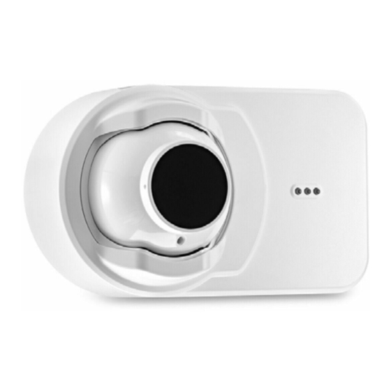
OSI-RI-FL Installation Guide General Description The OSI-RI-FL is a long range projected beam smoke imaging detector designed to provide open area protection. It is to be used with listed (UL, EN54, etc.), control panels only. The detector consists of a transmitter/receiver unit and a reflector. - Page 12 OSI-RI-FL Installation Guide OSI-RI by Fire-Lite Alarms This page is intentionally left blank. E56-6584-001 | October 2018...
-
Page 13: Special Applications
OSI-RI by Fire-Lite Alarms OSI-RI-FL Installation Guide Special Applications Due to the inherent capabilities of projected type beam detectors they are often installed in locations where spot-type detection is impractical. Projected type beam smoke detectors are ideally suited for environmental conditions that might include high ceilings or areas with difficult access to the ceiling. - Page 14 OSI-RI-FL Installation Guide OSI-RI by Fire-Lite Alarms This page is intentionally left blank. E56-6584-001 | October 2018...
-
Page 15: Approved Accessories
OSI-RI by Fire-Lite Alarms OSI-RI-FL Installation Guide Approved Accessories The following accessories can be purchased separately for use with this beam detector. 6500MMK The 6500MMK allows reflected beam detectors and reflectors to be mounted to either a vertical wall or the ceiling. The kit allows for additional alignment range in cases where the detector and reflector cannot be mounted within 10°... - Page 16 OSI-RI-FL Installation Guide OSI-RI by Fire-Lite Alarms This page is intentionally left blank. E56-6584-001 | October 2018...
-
Page 17: Package Contents
OSI-RI by Fire-Lite Alarms OSI-RI-FL Installation Guide Package Contents 1 Transmitter/Receiver Unit 1 Paintable Trim Ring 1 Reflector 4 Plug-in Terminal Blocks 2 Isolator Shunts 1 OSI-RI-FL Quick Start Guide E56-6584-001 | October 2018... - Page 18 OSI-RI-FL Installation Guide OSI-RI by Fire-Lite Alarms This page is intentionally left blank. E56-6584-001 | October 2018...
-
Page 19: Detector Placement
OSI-RI by Fire-Lite Alarms OSI-RI-FL Installation Guide Detector Placement This section of the manual discusses the placement of projected beam detectors. Though this information is based upon industry expertise, it is intended to be used only as a technical guide. - Page 20 OSI-RI-FL Installation Guide OSI-RI by Fire-Lite Alarms As a rule, reflective objects such as ductwork or windows should be a minimum of +/- 2° out of the center of the beam path of the beam. R e fe r to...
-
Page 21: Mounting Locations
OSI-RI by Fire-Lite Alarms OSI-RI-FL Installation Guide Mounting Locations Beam detectors require a stable mounting surface for proper operation. A surface that moves, shifts, vibrates, or warps over time will make the system prone to nuisance alarm or trouble conditions. Initial selection of a proper mounting surface will eliminate false alarms and nuisance trouble signals. - Page 22 OSI-RI-FL Installation Guide OSI-RI by Fire-Lite Alarms This page is intentionally left blank. E56-6584-001 | October 2018...
-
Page 23: Mounting Instructions
OSI-RI by Fire-Lite Alarms OSI-RI-FL Installation Guide Mounting Instructions Mounting the Reflector The reflector can be mounted to the wall using the supplied drilling template see (B Appendix II. Reflector Drilling Template). The reflector has 4 mounting holes, one in each corner. -
Page 24: Mounting The Imager
OSI-RI-FL Installation Guide OSI-RI by Fire-Lite Alarms 10° maximum Optical Line of Sight Reflector Figure 9-3: Reflector Mounting Guidelines Mounting the Imager The transmitter/receiver unit can be surface mounted, Cable knock-outs are provided top, bottom and back in the back box. -
Page 25: Mounting Considerations For Single Ended Beam Detectors
OSI-RI by Fire-Lite Alarms OSI-RI-FL Installation Guide 10 Mounting Considerations for Single Ended Beam Detectors There must be a permanent clear line of vision between the detector and the reflector. Reflective objects must not be near the line of vision between the detector and reflector. Reflective objects too near to the line of sight can reflect the light beam from the transmitter to the receiver. - Page 26 OSI-RI-FL Installation Guide OSI-RI by Fire-Lite Alarms This page is intentionally left blank. E56-6584-001 | October 2018...
-
Page 27: Wiring Installation Guidelines
OSI-RI by Fire-Lite Alarms OSI-RI-FL Installation Guide 11 Wiring Installation Guidelines Always install all wiring in compliance with the National Electrical Codes, and/or the applicable local codes, and any special requirements of the local authority having jurisdiction. Proper wire gauges and suitable means for strain relief should be used. - Page 28 OSI-RI-FL Installation Guide OSI-RI by Fire-Lite Alarms Not Used Not Used Heater Power In - Heater Power In + AUX (-) Remote Test/Reset Input Remote Trouble Output Remote Alarm Output Connector SLC - OUT SLC - IN SLC + OUT...
- Page 29 OSI-RI by Fire-Lite Alarms OSI-RI-FL Installation Guide T2-1 Alarm Signal Circuit T2-2 Trouble Signal Circuit T2-4 Yellow Remote LED connections Figure 11-5: Wiring Diagram (Remote LEDs) E56-6584-001 | October 2018...
- Page 30 OSI-RI-FL Installation Guide OSI-RI by Fire-Lite Alarms This page is intentionally left blank. E56-6584-001 | October 2018...
-
Page 31: Installation/Alignment
For longer distances or in heavy lit environments use the OSP-002 Laser Alignment tool to roughly align the OSI-RI-FL eyeball with the reflector. Make sure there are no people or objects obstructing your view of the reflector. This is also a good time to confirm that there are no obstructions or reflective objects within 15”... -
Page 32: Fine Adjustment
OSI-RI-FL Installation Guide OSI-RI by Fire-Lite Alarms 12.3 Fine Adjustment It is important to be well aligned as the IR power drops rapidly out of the centre of the beam. The maximum beam size is dependent on the distance (D) between detector and reflector and can be calculated as 0.07x D. -
Page 33: Completing The Installation
The detector should enter a trouble condition, indicated by the fault relay and the yellow LED (see A Appendix I. Operation Modes and Troubleshooting Guide OSI-RI-FL: ) after 30 seconds. If the detector does not enter a trouble condition, there is a problem with the installation. Refer to troubleshooting section in A Appendix I. - Page 34 OSI-RI-FL Installation Guide OSI-RI by Fire-Lite Alarms This page is intentionally left blank. E56-6584-001 | October 2018...
-
Page 35: Testing And Determining The Sensitivity Of The Unit
The LEDs at the remote test station will mimic the detector front LEDs. Note: For the OSI-RI-FL this test does not satisfy the requirements of NFPA72 for periodic maintenance and sensitivity verification of beam type detectors. E56-6584-001 | October 2018... - Page 36 OSI-RI-FL Installation Guide OSI-RI by Fire-Lite Alarms For the OSI-RI-FL this test in conjunction with the complete reflector blockage test (see step 4 of the Installation/Alignment procedure in this manual) does satisfy the requirements of NFPA72 for periodic maintenance and sensitivity verification of beam type detectors.
-
Page 37: Operation After A Power Failure
OSI-RI by Fire-Lite Alarms OSI-RI-FL Installation Guide 14 Operation After A Power Failure The detector has the reflector location/position, set sensitivity and other commissioning parameters permanently memorised after the initialisation process. After a power failure of any duration, when the supply is restored the detector will check the possible new situation versus it memorised data. - Page 38 OSI-RI-FL Installation Guide OSI-RI by Fire-Lite Alarms This page is intentionally left blank. E56-6584-001 | October 2018...
-
Page 39: Maintenance
OSI-RI by Fire-Lite Alarms OSI-RI-FL Installation Guide 15 Maintenance Note: Before cleaning the detector, notify the proper authorities that the smoke detector system is undergoing maintenance, and therefore the system will be temporarily out of service. Disable the zone or system undergoing maintenance to prevent unwanted alarms. - Page 40 OSI-RI-FL Installation Guide OSI-RI by Fire-Lite Alarms This page is intentionally left blank. E56-6584-001 | October 2018...
-
Page 41: Painting
OSI-RI by Fire-Lite Alarms OSI-RI-FL Installation Guide 16 Painting The outer aesthetic ring may be painted using a spray or brush type paint of appropriate type. For more information refer to section 1. Note: Never paint the flat lens surface of the imager. - Page 42 OSI-RI-FL Installation Guide OSI-RI by Fire-Lite Alarms This page is intentionally left blank. E56-6584-001 | October 2018...
-
Page 43: Special Note Regarding Smoke Detector Guards
OSI-RI by Fire-Lite Alarms OSI-RI-FL Installation Guide 17 Special Note Regarding Smoke Detector Guards Smoke detectors are not to be used with detector guards unless the combination has been evaluated and found suitable for that purpose. E56-6584-001 | October 2018... - Page 44 OSI-RI-FL Installation Guide OSI-RI by Fire-Lite Alarms This page is intentionally left blank. E56-6584-001 | October 2018...
-
Page 45: A Appendix I. Operation Modes And Troubleshooting Guide Osi-Ri-Fl
OSI-RI by Fire-Lite Alarms OSI-RI-FL Installation Guide A Appendix I. Operation Modes and Troubleshooting Guide OSI-RI-FL: Red and Remote Yellow and Remote Modes Green Initiating means Comments and Troubleshooting Tips Alarm Output Trouble Output Power On Blink Apply Power from discharged state. - Page 46 OSI-RI-FL Installation Guide OSI-RI by Fire-Lite Alarms Blink patterns 1. OK/Green: Imager will flash green once every 5 seconds. 2. Alarm/Red: Imager red solid on. 3. Faults/Yellow: Number of pulses identifies type of fault. Rhythm; every pulse 15ms ON/15ms OFF, repeat after 2 seconds till fault has disappeared.
-
Page 47: B Appendix Ii. Reflector Drilling Template
OSI-RI by Fire-Lite Alarms OSI-RI-FL Installation Guide B Appendix II. Reflector Drilling Template 5.512” (140mm) 8.465” (215mm) Scale = 1:1 FCC STATEMENT This device complies with part 15 of the FCC Rules. Operation is subject to the following two conditions: (1) This device may not cause harmful interference, and (2) this device must accept any interference received, including interference that may cause undesired operation. -
Page 48: Iv E56-6584-001 | October
Fire-Lite Alarms warrants its enclosed smoke detector to be free from defects in materials and workmanship under normal use and service for a period of three years from date of manufacture. Fire-Lite Alarms makes no other express warranty for this smoke detector.
Need help?
Do you have a question about the OSI-RI-FL and is the answer not in the manual?
Questions and answers