Table of Contents
Advertisement
Available languages
Available languages
Your Complete Satisfaction is Our Number One Goal.
At Pilot, your satisfaction is why we're in business.
If for any reason your experience with our product was
anything less than satisfactory, please reach out to us.
We'd love to have the opportunity to provide the product
experience and service you deserve.
Votre entière satisfaction constitue notre objectif principal.
Chez Pilot, nous sommes en affaires pour assurer votre
satisfaction. Si jamais, pour quelque raison que ce soit, votre
expérience avec un de nos produits ne s'avère pas entièrement
satisfaisante, n'hésitez pas à communiquer avec nous. Nous ne
demandons pas mieux que d'avoir l'occasion de vous procurer
l'expérience et le service auxquels vous avez droit.
Su completa satisfacción es nuestra meta número uno.
En Pilot, su satisfacción es la razón por la que estamos
en el negocio, sí por alguna razón su experiencia con nuestro
producto no fue satisfactoria, comuníquese con nosotros, nos
encantaría tener la oportunidad de brindarle
la experiencia y el servicio que usted se merece.
800. 237. 7560 • csteam@pilotautomotive.com
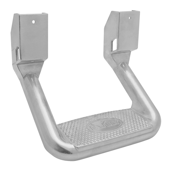
SIDE STEP
Installation Instructions
ÉTAPE LATÉRALE
Instructions d'installation
ESCALÓN LATERAL
Instrucciones de instalación
These instructions cover the following part numbers:
Ces instructions concernent les numéros de pièce ci-dessous:
Estas instrucciones aplican a los siguientes números de parte:
AS-600 ▪ AS-600S ▪ AS-600SB ▪ AS-600WK ▪ AS-600SZ
BBS-1103SZ ▪ BBS-1103 ▪ 34-2092-8 ▪ 34-2097-8
NOTE: For Dodge RAM 09-18 application only, please see page 10.
Remarque : Pour les modèles Dodge RAM 2009 à 2018 seulement,
veuillez consulter la page 20.
NOTA: Para aplicarse solamente en RAM 09-18, por favor
consulte la página 30.
Advertisement
Table of Contents

Related Manuals for Bully AS-600

Summary of Contents for Bully AS-600
- Page 1 Estas instrucciones aplican a los siguientes números de parte: producto no fue satisfactoria, comuníquese con nosotros, nos AS-600 ▪ AS-600S ▪ AS-600SB ▪ AS-600WK ▪ AS-600SZ encantaría tener la oportunidad de brindarle la experiencia y el servicio que usted se merece.
-
Page 2: Table Of Contents
INDEX ENGLISH Vehicle body diagram .....................2 Tools Needed ......................3 Instructions for group A, B, C .................4 Diagram for group A, B, C ..................5 Installation instructions & Diagram group D ............6 Instructions for group E ..................7 Diagram group E ....................8-9 Installation instructions for RAM 09-18 models only ......... -
Page 3: Tools Needed
( x2 ) ( x2 ) ( x2 ) 2.75" M8 x 1.25 Spacer IMPORTANT: Bully assumes no liability for any damage or injury caused Screw by customer's failure to adhere to the warnings and the directions in these instructions. -
Page 4: Instructions For Group A, B, C
English English INSTALLATION INSTRUCTIONS FOR GROUP A, B, C : 1. Find a proper position to mount the step. NOTE: For correct placement, the center of the step should be in line with the front edge of the seat's frame, also the step's Metal Body Figure A mounting plate should be able to lay flat against the vehicle’s rocker panel. -
Page 5: Installation Instructions & Diagram Group D
English English INSTALLATION INSTRUCTIONS GROUP E: INSTALLATION INSTRUCTIONS GROUP D: 1. Find the proper position to mount the step. NOTE: For correct placement, the 1. Review the diagrams of Group E on the following page (see E-2 & E-4) for center of the step should be in line with the front edge of the seat's frame, also the proper application. - Page 6 English English 11. Install the “C” brackets back into the mounting position. Insert sheet metal screws through the top holes and tighten, insert the 5/16" bolts through the bottom holes to hold on t the brackets to the vehicle. Add washers and nuts, do not tighten down Figure E-3 yet.
-
Page 7: Installation Instructions For Ram 09-18 Models Only
English English INSTALLATION INSTRUCTIONS FOR ram 09-18 models only : For applications that require hole to be drilled NOTE: Drilling required. Follow the drilling instructions on page 11. 1. Measure 2" from the bottom of the hole already drilled out and 1 1/16"... -
Page 8: Français
FRANÇAIS FRANÇAIS ILLUSTRATIONS DES GROUPES DE CARROSSERIE OUTILS REQUIS : AVANT D’ENTREPRENDRE L’INSTALLATION : Examinez le bas de caisse de votre • Tournevis Phillips n° 2 (long et court) véhicule pour déterminer le groupe de carrosserie auquel il appartient • Perceuse électrique avec forets (1/8, 1/4, 3/8) (voir les illustrations). -
Page 9: Instructions Pour Les Groupes A, B Et C
FRANÇAIS FRANÇAIS INSTRUCTIONS D’INSTALLATION POUR LES GROUPES A, B ET C : 1.Repérez un bon endroit pour monter le marchepied. Remarque : Pour un bon ajustement, le centre du marchepied doit être aligné avec le rebord avant de l’armature du siège et la Carrosserie Figure A plaque de montage du marchepied doit pouvoir reposer à... -
Page 10: Illustrations Pour Le Groupe E
FRANÇAIS FRANÇAIS INSTRUCTIONS D’INSTALLATION POUR LE GROUPE E : INSTRUCTIONS D’INSTALLATION POUR LE GROUPE D : 1. Repérez un bon endroit pour monter le marchepied. Remarque : Pour un bon ajustement, 1. Examinez les illustrations pour le groupe E à la page suivante (voir les figures E-2 et E-4) le centre du marchepied doit être aligné... - Page 11 FRANÇAIS FRANÇAIS 11. Remettez les supports en C à leur position de montage. Insérez les vis à tôle dans les rous supérieurs et serrez-les. Insérez les boulons de 5/16 po dans les trous inférieurs pour fixer les supports au véhicule. Ajoutez les rondelles et les écrous, mais ne les serrez pas tout Figure E-3 de suite (voir les figures E-2 et E-4).
-
Page 12: Instructions D'installation Pour Modèles Ram 2009 À 2018 Seulement
FRANÇAIS FRANÇAIS INSTRUCTIONS D’INSTALLATION POUR MODÈLES RAM 2009 À 2018 SEULEMENT : POUR LES MODÈLES NÉCESSITANT LE PERÇAGE D’UN TROU Remarque : Perçage requis. Veuillez suivre les instructions de perçage à la page 21. 1. Mesurez 2 po à partir du bas du trou déjà perforé et 1 1/16 po à partir du rebord, puis marquez cet emplacement. -
Page 13: Español
( x2 ) ( x2 ) Tornillo de Tuerca de Espaciador IMPORTANTE: Bully no asume ninguna responsabilidad por daños o lesiones 6,98 cm M8 x 1.25 causados por el incumplimiento y no seguimiento de las advertencias e instrucciones de este manual. - Page 14 ESPAÑOL ESPAÑOL c. Coloque las cuñas de nuevo en su lugar, taladre un agujero de 3,17 mm (1/8") INSTRUCCIONES DE INSTALACIÓN PARA LOS GRUPOS A, B, C: a través del escalón y la cuñas al cuerpo de metal, use los tornillos para metal 1.
- Page 15 ESPAÑOL ESPAÑOL INSTRUCCIONES DE INSTALACIÓN PARA EL GRUPO E: INSTRUCCIONES DE INSTALACIÓN PARA EL GRUPO D: 1. Encuentre la posición apropiada para montar el escalón. NOTA: Para una colocación correcta, 1. Revise los diagramas del Grupo E en la página siguiente (ver E-2 y E-4) para una el centro del escalón debe estar alineado con el borde delantero del bastidor del asiento, aplicación correcta.
- Page 16 ESPAÑOL ESPAÑOL 11. Instale los soportes "C" nuevamente en la posición de montaje. Inserte los tornillos de metal a través de los orificios superiores y apriételos, inserte los tornillos de 7,94 mm (5/16") a través de los orificios inferiores para sujetar los soportes al vehículo, agregue las FIGURA E-3 rondanas y las tuercas, no las apriete (ver Fig.
- Page 17 ESPAÑOL ESPAÑOL INSTRUCCIONES DE INSTALACIÓN SOLAMENTE PARA MODELOS RAM 09-18: PARA APLICACIONES QUE REQUIEREN QUE SE TALADRE UN HOYO NOTA: Requiere perforación. Siga las instrucciones de taladrado en la página 31. 1. Mida 5,08 cm desde la parte inferior del agujero ya hecho y 2,69 cm de la orilla y marque el lugar.
Need help?
Do you have a question about the AS-600 and is the answer not in the manual?
Questions and answers