
Related Manuals for Hydra-Flex AQUA-LAB AX

Summary of Contents for Hydra-Flex AQUA-LAB AX
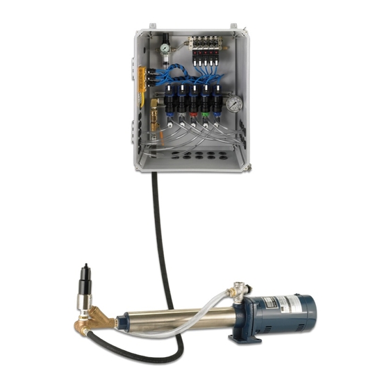
- Page 1 AQUA-LAB AX, BX, TX ™ CHEMICAL DISPENSING SYSTEM User Manual REV A 4000133 revA0717 © Hydra-Flex, Inc. 2017 © Hydra-Flex, Inc. 2017...
-
Page 2: Table Of Contents
TABLE OF CONTENTS Overview Features Specifications Installation Instructions Installation Specifications Unpacking Location and Mounting Feed Water Connection Chemical Line Connections Pneumatic Connections Electrical Connections Operation Pump Priming Instructions Water Flow Rate and Chemical Dilution Set Up Post Installation Vacuum & Back Pressure Check Chem-Flex Injector Vacuum Check Chem-Flex Back Pressure Check Individual Injector Flow Rate Measurement Troubleshooting Appendix Chemical Metering & Dilution Charts Terminal Box Wiring Instructions (Optional) Replacement Panel, Pump, & MCU Parts List FOR ADDITIONAL SUPPORT CALL 952-808-3640 OR VISIT US ON THE WEB: www.hydraflexinc.com © Hydra-Flex, Inc. 2017... -
Page 3: Overview
Up to 15 Pneumatic Ports • Hydraulics operating pressure: 200 psi (Factory set) • Pneumatics operating pressure: 100 psi (Factory set) • Operating Ambient Temperature: 40-120 Deg F • Operate pumps with 208/230 or 480 Voltages (3-phase) • Operate Solenoid Valves with 24VAC, 24VDC, 120VAC • 1-1/2” water supply line (TX Model) • 1” water supply line (AX & BX Models) • Inlet pressure: 2-80 psi • Space Requirements: a. Aqua Lab Systems i. TXF Model – 3’ x 3’ footprint with 5’ Clearance ii. TXW Model – 2’ wide x 4.5’ high of wall space for system iii. AX Model – 3’ wide x 2’ high of wall space for system iv. BX Model – 1.5’ wide x 2’ high of wall space for system b. Pump Assemblies – Pumps need to be within 3’ of the system to allow connection of the two with just the included connection hose i. Single Pump – 4’ x 1’ wall space ii. Dual Pump Wall mount – 4’ x 3’ of wall space iii. Dual Pump Floor skid – 4’ wide x 1.5’ deep footprint with 4’ of Clearance c. Electrical Enclosures i. Motor Starter (AX and BX Models) – 1’ wide x 1.5’ high of wall space ii. VFD Motor Controller – 1.5’ wide x 2’ high of wall space iii. Terminal Box (Accessory) – 1’ wide x 1’ high of wall space Page | 1 © Hydra-Flex, Inc. 2017... -
Page 4: Installation Instructions
Unpacking: Normal hand tools • Assembly: Normal hand tools • Wiring: Normal electrical wiring tools • Startup: Electrical meter helpful but not required ESTIMATED TIMELINE: • Unpacking: 15 – 30 minutes • Frame Mounting: 0.5 – 2.0 hours • Fluid Connections: 0.5 – 2.0 hours • Motor & Valve Wiring: 1 – 4.0 hours • Startup & adjustment: 1.5 – 6.0 hours UNPACKING The AQUA-LAB is shipped in a wooden crate for the purpose of protection. Before unpacking, be sure that the AQUA-LAB is on a level-flat surface. To unpack, perform these steps: 1. Open the crate using a drill with Phillips bit or Phillips head screwdriver 2. Cut the cellophane off of the AQUA-LAB by using a utility knife. Be sure to cut either at the corners or in an area where the knife will not damage the AQUA-LAB. 3. Using an adjustable wrench, un-bolt the AQUA-LAB from the pallet. 4. Lift the AQUA-LAB from the pallet. Use assistance if necessary. 5. Dispose of pallet, cellophane and additional packaging materials. Page | 2 © Hydra-Flex, Inc. 2017... -
Page 5: Location And Mounting
Aqua-Lab Systems • TXF – Position on the floor in optimal location, can be anchored with included anchor feet • TXW – Mount to concrete or cinder block wall with 4 concrete anchors • AX – Mount to concrete or cinder block wall with 4 concrete anchors • BX – Mount sturdy wall with 4 appropriate anchors Pump Assemblies – Does not apply to TXF • Single Pump – Mount pump flange to concrete or cinder block wall or concrete floor with 4 concrete anchors – **Needs to be within 3’ of the Aqua-Lab system to connect them with the included connection hose • Dual Pump Wall mount – Mount to concrete or cinder block wall with 4 concrete anchors – **Needs to be within 3’ of the Aqua-Lab system to connect them with the included connection hose • Dual Pump Floor skid – Position on the floor near the feed water connection – **Needs to be within 3’ of the Aqua-Lab system to connect them with the included connection hose Electrical Enclosures • Motor Starter – (Pre mounted to the Frame for TXF) for other systems mount to the wall with 4 appropriate anchors • VFD Motor Controller – (Pre mounted to the Frame for TXF) for other systems mount to the wall with 4 appropriate anchors • Terminal Box (Accessory) – Mount to wall with 4 appropriate anchors – **Location will depend on the position of the Aqua-Lab system and its proximity to the car wash control cabinet Page | 3 © Hydra-Flex, Inc. 2017... -
Page 6: Feed Water Connection
**IF AIR IS NOT REQUIRED FOR YOUR AQUA-LAB, PLEASE SKIP THIS SECTION Pneumatic Utility Connections: • Flow and Pressure: 20 CFM, 100 PSI Max (Primary Regulator Factory Set, do not adjust) • Incoming Connection Type and Size: 3/8” OD Hose Push Fitting • Filter Included: Yes • Regulator Included: Yes (Primary Regulator Factory Set, do not adjust) • Lubricator Included: No • Outgoing Connection Type and Size: 1/4” OD Hose – Push to Connect • Air Pressure Control: Individual Adjustable Regulators • Air Flow Control: No **If there are unused air ports, either screw out the individual line regulator until air no longer flows or insert supplied plugs Page | 4 © Hydra-Flex, Inc. 2017... -
Page 7: Electrical Connections
BOX LABEL CABLE WIRE COLOR POSITION* Ground Green/Yellow Neutral / Common Blue DO NOT USE Brown Station 1 White Station 2 Green Station 3 Yellow Station 4 Grey Station 5 Pink DO NOT USE Page | 5 © Hydra-Flex, Inc. 2017... -
Page 8: Operation
5. TX Model: Slowly open the priming ball valve located off the end of the distribution block and allow water to flow until steady, then close the valve (a hose could be connected to the valve to the drain to avoid excessive water on the floor) 6. AX and BX Models: With the pump off disconnect the high pressure line to the AquaLab at the quick disconnect and point in a safe direction, while holding the line to control it start the pump and allow water to flow until steady. 7. Close the ball valve (TX Model) or reconnect the high pressure line at the quick disconnect (AX and BX Models) 8. Confirm that the pumps can obtain 200 psi and that the pump housing is cool to the touch after a minute in operation. 9. If pump does not prime, repeat steps 3-6 • !!Pay close attention to the temperature of the pump housing, if it starts getting hotter than the supply water then it is likely that the pump did not prime correctly!! • *WARNING* If the pumps do not prime correctly they will heat up and it will cause damage to the pumps. WATER FLOW RATE AND CHEMICAL DILUTION SET UP For each of the chemicals that the Aqua-Lab is delivering to the car wash bay follow the steps outlined below to set the overall flow rate and chemical dilution. NOTE: you will need to know the target flow rate and chemical dilution (concentration) prior to setting up each chemical. Page | 6 © Hydra-Flex, Inc. 2017... -
Page 9: Post Installation Vacuum & Back Pressure Check
1. Disconnect the outlet hose from the Chem-Flex injector that a back pressure reading will be taken for. 2. Connect the back pressure gauge assembly to the outlet of the Chem-Flex injector. 3. Connect the hose to the arch to the other end of the back pressure gauge assembly. **Make sure all hose barb fittings are secured with hose clamps. 4. Turn on the Aqua-Lab pump and the solenoid valve for the Chem-Flex being tested from the main car wash control cabinet – The back pressure should not exceed 33% of the feed pressure (for the Aqua-Lab with the feed pressure set to 200 psi the back pressure should not exceed 66 psi). 5. Turn off the Aqua-Lab pump and solenoid valve at the main car wash control cabinet. 6. Remove the back pressure gauge assembly from the injector and reconnect the hose to the arch. **Make sure all hose barb fittings are secured with hose clamps. 7. Repeat steps 1-5 for each injector that a back pressure reading is needed for. Page | 7 © Hydra-Flex, Inc. 2017... -
Page 10: Individual Injector Flow Rate Measurement
Worn o-ring seals Replace Injector is not drawing chemical - Passes Check chemical hose, foot valve, meter- Clogged chemical feed Vacuum Pressure check test ing tip and hose barb for debris or clogs Page | 8 © Hydra-Flex, Inc. 2017... - Page 11 No water supply water Valve stuck open – Staying open when Remove and clean valve (See valve Debris in valve seat signal is off replacement instructions) VALVE REPLACEMENT INSTRUCTIONS Remove malfunctioning valves from the manifold making sure to unscrew it from the larger steel hex closest to the plastic body. On a clean work surface disassemble the valve assembly. Be cautious with the small components and noting how it is assembled. Inspect for debris that could interfere with the valves operation, paying particular attention to anything blocking the two small holes through the valve piston (2nd part from the left in the image below). For and correct assembly reference the image below. Page | 9 © Hydra-Flex, Inc. 2017...
-
Page 12: Appendix
APPENDIX: CHEM-FLEX INJECTORS - CHEMICAL DILUTION RATIOS Page | 10 © Hydra-Flex, Inc. 2017... -
Page 13: Terminal Box Wiring Instructions (Optional)
4. Using a small screwdriver, press into the spring terminal and pull away from the wire terminal to open the spring clamps. Insert the wire that corresponds to the labeled color then release the spring by removing the screw driver (Figure 4) Figure 4 5. Repeat for all colors labeled. (brown and red are not used) 6. Blue and Green/Yellow are to be wired to the common and ground terminals which are segmented as shown (Figure 5) Figure 5 7. Repeat for all yellow Aqua-Lab cables 8. Individually insert chemical activation signals through cable glands and wire to desired chemical position (see wiring chart in operations manual) (Figure 6). 9. Repeat for all chemical signals, only one of the common (blue) and ground (Green/yellow) wires for the signals need to be wired to the Figure 6 corresponding segmented terminals since they should be previously connected at the wash controller. You can wire up to three of the commons and grounds to ensure a redundant connection. 10. Lightly tug on all wires to ensure a good connection. 11. Replace Cover and tighten screws Figure 7 Page | 11 © Hydra-Flex, Inc. 2017... -
Page 14: Replacement Panel, Pump, & Mcu Parts List
REPLACEMENT PANEL, PUMP, & MCU PARTS LIST - AQUA-LAB AX/BX/TX Page | 12 © Hydra-Flex, Inc. 2017... - Page 15 40 GPM Bypass Pressure Regulator - Stainless Steel 3000464 Manifold Inlet 1/2” ID Hose X 1/2” NPT Ends - 72” Long 3000579 20 GPM Quick Connect Regulator Plumbing Assembly 1001775 Replacement/Backup 20 GPM Pump 1001362 Outlet Manifold 3000662 1” Check Valve - Brass 3000250 Quick Connect 9’ Cordset For Pump 3000782 Quick Connect Pump Plug - Female 3000783 Thermal Overload - Sprecher & Schuh 3000862 Timer Relay 3000664 Current Sensor - AC 3000666 Current Sensor - DC 3000866 24 VAC 3000863 Contactor - Sprecher & Schuh 24 VDC 3000864 120 VAC 3000865 M12 Cordset (Grey) 3000347 3/4” x 72” Hose 3000659 Page | 13 © Hydra-Flex, Inc. 2017...
- Page 16 Page | 14 T: 952-808-3640 • F: 952-808-3650 • www.hydraflexinc.com • sales@hydraflexinc.com © Hydra-Flex, Inc. 2017 4000133 revA0717...
Need help?
Do you have a question about the AQUA-LAB AX and is the answer not in the manual?
Questions and answers