
Related Manuals for BNC RTSA7550


Summary of Contents for BNC RTSA7550
- Page 1 Berkeley Nucleonics RTSA7550 Real-Time Spectrum Analyzer User Guide Version 4.0 Berkeley Nucleonics Corporation - 2955 Kerner Blvd. - San Rafael, CA 94901 800-235-7858 or LiveChat @ www.berkeleynucleonics.com...
- Page 2 Customer. BNC will warrant electronic, mechanical, repaired units for a period of 90 days from date of shipment from BNC to the recording, or otherwise, Customer. If the remaining period on the original hardware warranty is greater than for any purpose, without 30 days, then BNC will honor this remaining warranty period.
-
Page 3: Table Of Contents
Connecting to the RTSA7550 ..................... 13 Deciding on Your Network Topology and IP Address Allocation ............13 Changing the Method of IP Address Allocation for the RTSA7550 analyzer ......... 14 Connecting the RTSA7550 Analyzer Directly to a Computer ..............14 Connecting to the RTSA7550 Analyzer Across a Network .............. - Page 4 Power (PWR) Indicator LED ......................30 Status (STS) Indicator LED ......................30 10 MHz Reference (REF) Clock Source and Lock Indicator LED ............ 31 RF Chain PLLs LOCK Indicator LED ....................31 Ethernet LINK Status and ACT Indicator LEDs ................31 Hardware Reference ....................
-
Page 5: Preface
Info@berkeleynucleonics.com. Thank you, we appreciate your comments. Obtaining Technical Assistance The BNC Support website provides online documents for resolving technical issues with BNC products at https://www.berkeleynucleonics.com/support. Berkeley Nucleonics Corporation - 2955 Kerner Blvd. - San Rafael, CA 94901 800-235-7858 or LiveChat @ www.berkeleynucleonics.com... - Page 6 9 AM to 5 PM Eastern Time, Monday to Friday. Contact us at Info@berkeleynucleonics.com or by calling +1 415-453-9955 Before contacting Support, please have the following information available: RTSA7550 serial number which is located on the identification label on the RTSA7550's underside. The product version. ...
-
Page 7: Overview Of The Bnc Rtsa7550
The RTSA7550 Real-Time Spectrum Analyzer provides Gigabit Ethernet for stand-alone, remote and distributed applications. BNC supports a rich set of industry-leading standard protocols and APIs, enabling the RTSA7550 to easily integrate into your new or existing applications. Standard protocols include the Standard Commands for Programmable... -
Page 8: Getting Familiar With The Bnc Rtsa7550
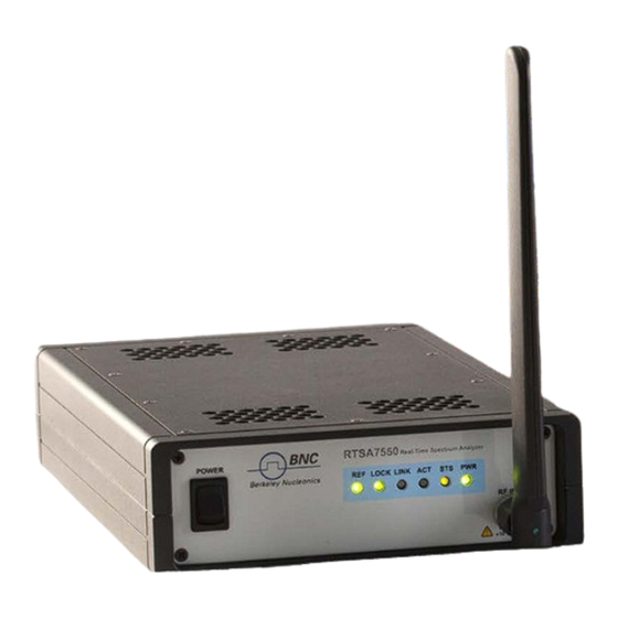
The Front Panel The front panel of the RTSA7550 (the left side of the picture above) contains the power switch, status indicator LEDs and input connectors for the RF antenna and analog IQ ports. - Page 9 Overview of the BNC RTSA7550 BNC RTSA7550 Real-Time Spectrum Analyzer User Guide Berkeley Nucleonics Corporation - 2955 Kerner Blvd. - San Rafael, CA 94901 800-235-7858 or LiveChat @ www.berkeleynucleonics.com...
-
Page 10: Installing The Bnc Rtsa7550
Unpacking the Box The following table lists the items that come with your RTSA7550 analyzer. If any of the items are missing or damaged, please contact your BNC customer service representative. -
Page 11: Connecting The Antenna, Ethernet And Power Cables
1. Screw the antenna on to the RTSA7550 "RF IN" antenna input SMA jack. Carefully turn the antenna screw by hand until it encounters resistance. See System Specifications for the maximum allowable input and cautions. -
Page 12: Selecting Where To Mount The Rtsa7550
Selecting Where to Mount the RTSA7550 Caution: To prevent damage to the RTSA7550 radio receiver, do not install or operate the RTSA7550 within 2 feet (60 cm) of devices such as Wi-Fi access points that transmit more than +15 dBm power. -
Page 13: Connecting To The Rtsa7550
Ethernet port and obtaining its IP address. Deciding on Your Network Topology and IP Address Allocation Note: To connect with the RTSA7550 analyzer via its Ethernet port, you must decide on both the topology of your network connection and how your RTSA7550 obtains its IP address. -
Page 14: Changing The Method Of Ip Address Allocation For The Rtsa7550 Analyzer
This section provides instruction on connecting the RTSA7550 analyzer directly to a computer via their Ethernet ports using an Ethernet cable. In order to connect directly to a RTSA7550, the host PC might require a spare Ethernet interface that is not otherwise used as its primary network connection. For example, you may use a wireless connection for primary network connectivity or obtain a second Ethernet card or USB adapter to connect to the RTSA7550. - Page 15 STS LED for the Auto-IP setup completion (take a minute or longer). Note: While the RTSA7550 is searching for a DHCP server, the STS LED blinks yellow slowly until it obtains an IP address either via DHCP or Auto-IP. The STS LED blinks in a green heartbeat pattern if it has set up successfully to using an Auto-IP address.
-
Page 16: Connecting To The Rtsa7550 Analyzer Across A Network
1. Decide on whether you will be using static or dynamic IP allocation. Both your PC and the RTSA7550 do not need to be configured for the same method of IP allocation; although to locate your RTSA7550 using the BNC Discovery tool requires that they be on the same subnet. - Page 17 4. Check to ensure that either your router's or the RTSA7550's LINK indicator is illuminated. 5. If your RTSA7550 is behind a firewall or a router with firewall capability, then your network's DHCP server is likely assigning private IP addresses (e.g. 192.168.x.x, 10.x.x.x, 172.x.x.x), and the firewall is likely providing some form of network...
-
Page 18: Administration Console
RTSA7550's MAC address, hardware and software versions. Configuring the RTSA7550 Time The time on the RTSA7550 analyzer can be set manually or as per host PC's time or via an NTP server. BNC RTSA7550 Real-Time Spectrum Analyzer User Guide Berkeley Nucleonics Corporation - 2955 Kerner Blvd. - Page 19 Administration Console Note: The RTSA7550 analyzer stores its time based on the Coordinated Universal Time (UTC) and otherwise has no notion of local time-zones. Conversely, the web dialog translates and displays the RTSA7550 time based on the local time-zone setting of the PC.
-
Page 20: Configuring The Rtsa7550 Ip Address
DHCP or is set manually to a static address. Caution: Please note that if the RTSA7550 IP address is set to static IP then the only way to communicate with the RTSA7550 is via that IP address. If you mistakenly enter the wrong IP address and/or subnet mask, or forget the IP address, then you can Restarting the RTSA7550. - Page 21 1. Click on the "Firmware Install" link in the left column menu of the administrative console. The following "Firmware Install" web page should appear. Warning: Do not unplug the RTSA7550 during a firmware update or the device may become inoperable.
-
Page 22: Customizing The Rtsa7550 Calibration
Note: If the RTSA7550 is not restarted immediately after a firmware install process, then the newly installed firmware will take effect upon the next restart of the RTSA7550 regardless of whether it is a software restart or a power-on reset. -
Page 23: Uploading A Custom Calibration File
You can upload your custom calibration settings file to the RTSA7550 via the administrative console. Note: You must restart the RTSA7550 for the new calibration settings to take effect. Note: Custom calibrated values might get over-written by a new firmware update. After... -
Page 24: Calibration File Source Selection
See the following picture for example. Calibration File Source Selection When more than one calibration settings file are present in the system, the RTSA7550 selects the calibration source using the following priority: 1. Firmware version specified in the calibration file 2. -
Page 25: Restarting The Rtsa7550
Please check with your network administrator to determine the IP address of the RTSA7550. This might happen only when the unit is not in static IP mode or a factory reset has been done to the unit. -
Page 26: Reset To Factory Settings
Follow the steps below to reset your box. 1. Power on the RTSA7550 2. At any time while the RTSA7550 is powered on, press and hold the reset button (locate in the rear panel of the box) for at least 5 seconds by inserting a paper clip or similar object 3. -
Page 27: Using The Usb Console
COM Port driver, which may require configuration of drivers on your PC. 1. Power on the RTSA7550 and wait approximately 30 seconds to allow it to boot 2. Connect the USB cable to the RTSA7550 USB console port and your PC's USB port. -
Page 28: Configuring The Rtsa7550 Analyzer's Ip Address Via The Usb Console
VT100 terminal response. Repeatedly press “Ctrl+C” and “Enter” until the cursor appears. The cursor may take several seconds to appear. 6. Enter *IDN? command and press the “Enter” key. The RTSA7550 should return a message with its device identification such as “BNC, RTSA7550..”... - Page 29 Using the USB Console Caution: Please note that if the RTSA7550 IP address is set to static IP then the only way to communicate with the RTSA7550 is over the network via that IP address or via the USB console. Hence, if you mistakenly enter the wrong IP address and/or subnet mask,...
-
Page 30: Status Indicator Leds
One or more of the internal power conditions are not present or corrupted Status (STS) Indicator LED The STS indicator LED indicates the status of the RTSA7550 as it boots from power-on and/or reset and the network activity. STS Indicator LED... -
Page 31: 10 Mhz Reference (Ref) Clock Source And Lock Indicator Led
Ready for connection 10 MHz Reference (REF) Clock Source and Lock Indicator LED Referring to the above illustration, the REF LED indicates whether the RTSA7550 is using the internally generated 10 MHz reference clock or an external reference clock provided via the 10 MHz IN SMA connector, and whether that selected reference clock source is of sufficient quality for the internal PLL to lock to it. -
Page 32: Hardware Reference
This section provides physical and performance specifications, and port and cable pinouts for the RTSA7550. System Specifications The following table outlines the physical specifications for the RTSA7550 analyzer. Description Design Specification Dimensions (H x W x D without/D with rubber feet) 10.58 x 6.81 x 2.15/2.40 in. -
Page 33: Ethernet Rj-45 Port Pinout
(see the RTSA7550 Programmer's Guide), it is best to inject signals lower than -10 dBm. Additionally, any external signal sources connected to RF IN must be turned on only after powering on the RTSA7550 and turned off prior to powering down the RTSA7550. -
Page 34: Usb Console Port Pinout
VCC12V 9,15,21, 22 ground Note: The functionality of the EXT IN/OUT/IO pins is application specific and thus could vary. Refer to ThinkRF's Application Notes or contact BNC support for more information. USB Console Port Pinout 1 2 3 4 1 2 3 4... -
Page 35: Rj-45 Crossover Ethernet Cable
1 2 3 4 5 6 7 8 1 2 3 4 5 6 7 8 BNC RTSA7550 Real-Time Spectrum Analyzer User Guide Berkeley Nucleonics Corporation - 2955 Kerner Blvd. - San Rafael, CA 94901 800-235-7858 or LiveChat @ www.berkeleynucleonics.com...
Need help?
Do you have a question about the RTSA7550 and is the answer not in the manual?
Questions and answers