Table of Contents
Advertisement
Advertisement
Table of Contents

Related Manuals for Kolida K5 PLUS


Summary of Contents for Kolida K5 PLUS
- Page 1 K5 PLUS GNSS RECEIVER User Manual KOLIDA Instrument Company...
-
Page 2: Table Of Contents
§ 1.3 Features ........................- 5 - §1.4 Accessories &Components ..................- 7 - Chapter 2 K5 PLUS Measuring System ................... - 9 - §2.1 K5 PLUS Mainframe ..................... - 10 - §2.1.1 The mainframe appearance ................ - 10 - §2.1.2 Bottom interfaces .................. - Page 3 §4.2.4 Radio setting ....................- 62 - §4.2.5 Receiver register................... - 63 - Appendix A K5 PLUS main technical specifications ............- 64 - Appendix B GDL-20 radio technical specifications ............- 67 - Appendix C Technical Terms ..................... - 69 -...
-
Page 4: Chapter 1 Brief Introduction
K5 Plus GNSS Chapter 1 Brief Introduction Read this chapter, and you will have a brief knowledge of KOLIDA Company and K5 PLUS GNSS measurement system. § 1.1 Introduction Thanks for purchasing KOLIDA product! KOLIDA is a leading GNSS RTK and surveying instrument manufacturer, has been committed itself to spread the advanced survey techniques and products to users worldwide. -
Page 5: Features
970g, built with magnesium alloy materials. The top edge is designed to decrease the harm in case of falling down to ground. Dual module Bluetooth: K5 PLUS is equipped with Bluetooth 4.0 module, support communication with smart phone, tablet PC and other digital product. - Page 6 B1,B2 and B3 signal from BEIDOU, also can get positioning result with BEIDOU signal only. Smart and Open Platform: K5 PLUS is based on a smart and powerful platform which can make system works faster and more stable, less power consumption, also support smart voice guide and smart diagnosis etc.
-
Page 7: Accessories &Components
K5 Plus GNSS §1.4 Accessories &Components Rover station standard configuration Mainframe antennas S10 controller Measuring tape Mainframe charger Mainframe batteries Tribrach & connector Bracket for controllers Retractable pole multi-function communication cable - 7 -... - Page 8 K5 Plus GNSS Base station standard configuration Mainframe Antennas 25w radio Multiple communication cable Battery charger Batteries Tribrach & connector Communication cable Transmission antenna Support pole Frequency-change line Measuring tape - 8 -...
-
Page 9: Chapter 2 K5 Plus Measuring System
K5 Plus GNSS Chapter 2 K5 PLUS Measuring System Reading this chapter, you can grasp the components, installation and the function of K5 PLUS measuring system. Figure 2-1 ① Rover ② Controller ③Base ④ Tribrach ⑤ Radio ⑥Radio Antenna ⑦ Tripod ⑧Battery... -
Page 10: K5 Plus Mainframe
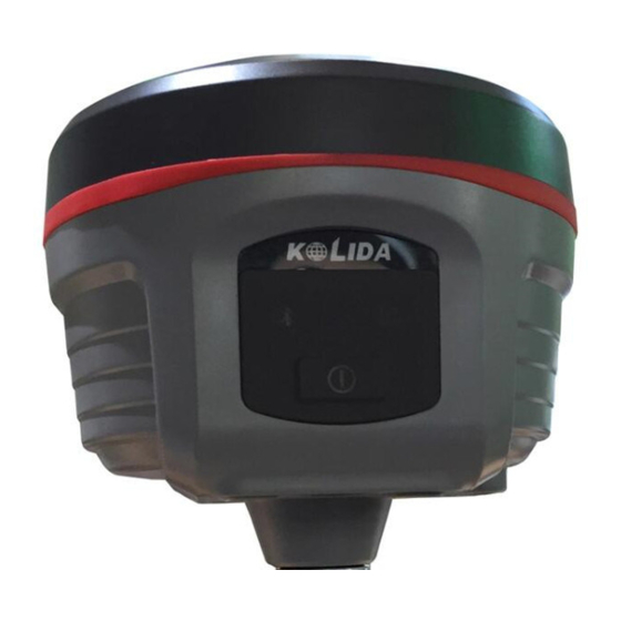
K5 Plus GNSS §2.1 K5 PLUS Mainframe §2.1.1 The mainframe appearance The mainframe is a flat cylindrical, 118mm in height, 134mm in diameter, the height from the rubber seal ring to the bottom is 78mm. The front side is the buttons and indicator panel. -
Page 11: Bottom Interfaces
K5 Plus GNSS Back Panel Figure 2-3 ① Battery compartment cover ②NFC label ③ Compartment locker Machine Serial number: for registration, and identify the instrument and the corresponding connection with data collector. §2.1.2 Bottom interfaces Figure 2-4 ① Compartment snap-fit: for locking the battery compartment cover ②... -
Page 12: Indicator Panel
In order to let you have a better understanding of the specific meaning of the indicator in the two status, we will describe in detail. K5 PLUS indicator panel has been re-designed with 3 LED indicators, simply and clearly indicates the various status, as shown below: Figure 2-5 ①3 indicator lights... -
Page 13: Mode Check And Switching
K5 Plus GNSS Indicator Status Meaning Normal voltage, built-in battery 7.4v POWER blink Low battery blink Number of satellite locked, cycle once every 5 seconds Satellite Handheld disconnected Bluetooth Handheld connected Static mode: flashing in accordance with the setting blink... -
Page 14: Self -Check
K5 Plus GNSS Figure 2-6 §2.1.5 Self -check If the panel indicator is abnormal or not working properly, you can use the automatic detection function to run the self-check. Power on, press and hold the <Power> button about 8 seconds, until the BT light turns on again and along with the beeping from receiver, then release the button to and the receiver starts performing the self-check. -
Page 15: Handheld Controller S10
K5 Plus GNSS The meaning of the lights during self-check Indicator Status Meaning Receiver is performing the self-check OEM board self-check is passed OEM board self-check isn’t passed GPRS/GSM module part self-check is passed GPRS/GSM module part self-check isn’t passed Internal radio module self- check is passed Internal radio module self- check isn’t passed... - Page 16 K5 Plus GNSS Figure 2-8 Standard Configuration Description Li-ion Battery 3.7V/ 3000 mA/h Strap Black, 180*12mm Touch Pen Black, 12.7mm - 16 -...
- Page 17 K5 Plus GNSS USB data cable 1.5m USB Charger 5V/1A Disc Table 2-3 Charging Connect the charger with collector by the USB Link cable to recharge. Main Screen (Upper right corner) will show the Charging Icon in power off (on) status.
- Page 18 K5 Plus GNSS Figure 2-10 Installing the battery, turn the lock clockwise to the end. (SIM Card: The Missing Angle Corner of SIM Card will be at the lower right corner) Power on/off Make sure that the battery is fully charged or you can connect the Collector to PC via the USB Cable.
- Page 19 K5 Plus GNSS After this, you can manage and edit the data in Collector. Installing Program Make sure that collector is synchronized with PC. Run the Installation file at PC side. If the installation program is also suitable for collector, you can copy the installation program into collector to install.
- Page 20 K5 Plus GNSS Figure 2-12 Camera Get into the Camera Mode by pressing the Camera Key for 3 or more seconds. Press Camera Key to take a photo and click “OK” on the screen to save. Figure 2-13 Note: If you want to know more information about S10, Please refer to S10 manual.
-
Page 21: Blue-Tooth Connection
K5 Plus GNSS §2.2.2 Blue-tooth connection The short-range wireless Bluetooth communication facilities are for the wireless exchange of information among a variety of Bluetooth-enabled devices. Tap on the Start menu (Settings) → (control panel) to open (Bluetooth Device Manager). tap on the(scanning device) after setting the Bluetooth device, and the surrounding Bluetooth devices will be listed in the search list. - Page 22 K5 Plus GNSS Figure 2-15 After pairing, select an available com port for the receiver (usually COM 8 and COM 5 are OK). As shown below: Figure 2-16 After the establishment of the virtual serial port, other applications can use the serial port for data communication with a Bluetooth device.
-
Page 23: Software Installation And Connecting
"Power Star", "Mapping Star", "Navigation Star” and so on. Here takes EGStar for example: EGStar is the specific software for K5 PLUS measuring system, mainly for the collection and calculation of the measuring points. Before installing EGStar, you need to install Microsoft Active Sync. After... - Page 24 K5 Plus GNSS status bar will display related data. If there is barrier, exit EGStar to reconnect (If the above settings are correct, then link directly). Handheld connecting with the host PC can do the follow-up measurement. Figure 2-18 2. Or go to “Bluetooth Manager”, in this interface tap on “Search” button and the controller will search the surrounding Bluetooth devices, select the correct serial number from the list and click on “Connect”...
-
Page 25: External Radio
The radio GDL20 is a high-speed semi-manual wireless data transmission radio, whose air transfer rate can be up to 19200 bps and the RF transmitter power is larger, used in KOLIDA RTK measurement system. Radio GDL20 adopts GMSK modulation, 19200bps transfer rate, low bit error rate. - Page 26 K5 Plus GNSS digital signal processing technology and baseband processing technology, carefully selected high quality components to organize production, to ensure the long-term stable and reliable operation; Have a forward error correction control, digital error correction function. It has eight transmitting and receiving channels. Can be changed according to the actual use of the channel frequency, transmit power adjustable interval is 0.5MHz...
-
Page 27: Radio Appearance
K5 Plus GNSS §2.3.2 Radio appearance Figure 2-20 ① Control panel ②SN number §2.3.3 Radio interface and panel Mainframe Interface: 5-pin jack for connecting GPS receiver and power supply Figure 2-21 5-pin port Antenna interface:For connecting the transmitter antenna Figure 2-22 Antenna interface... - Page 28 K5 Plus GNSS Control Panel: control panel lights display the status of the radio, the key operation is simple and convenient, one-to-one interface can effectively prevent connection errors. Figure 2-23 Control panel ① Channel indicator light. ② Power indicator light, ③...
-
Page 29: Radio Transmitting Antenna
K5 Plus GNSS Figure 2-24 Power switch §2.3.4 Radio transmitting antenna The UHF transmitting antenna is particularly suitable for field use, the receiving antenna is 450MHz Omni-directional antenna, light and durable. Figure 2-25 Radio antenna §2.3.5 Application Notice The battery power is too low: When the flashing channel indicator appears on the control panel, which means the lack of battery power, replace the battery in time, otherwise there would be data link unstable or unable to launch. - Page 30 K5 Plus GNSS the smaller the ripple factor is, the smaller will the beam spectrum be and the higher communication quality will be. Power Connection: Power of positive and negative connected correctly. Electromagnetic environment: Before using the radio, it is better to perform electromagnetic environment measurement, to avoid the communications blackout.
-
Page 31: Mainframe Accessories
K5 Plus GNSS §2.4 Mainframe accessories §2.4.1 Instrument Case The convenient RTK carrying case is customized for surveyors; it has strong abrasive resistance and waterproof ability. Meanwhile the unique backpack design reduces the heavy burden of field work. The inner layer of the black soft bag is filled with anti-collision foam, the host and other accessories can be dispersed and embedded;... -
Page 32: Differential Antennas
K5 Plus GNSS Figure 2-27 Charger& Adapter §2.4.3 Differential antennas Figure 2-28 GPRS antenna& UHF antenna The differential antennas are as shown above; UHF differential antenna is needed in UHF built-in radio base station mode and UHF built-in radio rover station mode. -
Page 33: Other Accessories
K5 Plus GNSS the base station mainframe (5-pin red jack), transmitting stations (black jack) and external battery (red and black clip) for power supply and data transmission. Figure 2-29 Power Cable Mainframe multi-function data cable: role multi-purpose communications cable is to connect the receiver to the host computer, for the transmission of static data and the host firmware upgrade. -
Page 34: Chapter 3 Operations
K5 Plus GNSS instrument upgrade. Chapter 3 Operations Reading this chapter, you can grasp in detail how to use the K5 PLUS measurement to do system static, RTK operations. GPS measurement operation scheme refers to the operating scheme used to determine the relative position between the stations with the help of GPS technology. -
Page 35: Static Operation
K5 Plus GNSS communication facilities (telephone telegraph, post telecommunications) and power supply, for power between the stations and equipments. §3.1 Static operation §3.1.1 Static Measurements Profile Static measurements: GPS positioning measurement by installed three (or more) GNSS receivers to perform simultaneous observation and determine the relative position between the stations. -
Page 36: Operating Procedures
K5 Plus GNSS §3.1.2 Operating procedures Pre-measurement Project approval Program design Construction design Surveying and mapping data collection and arrangement Instrument test, test Reconnaissance, choice of site, buried stone Measurement Operating team stationed in Satellite status Forecast Observation planning Dispatch of operation and field work observation... -
Page 37: Field Operation Notes
K5 Plus GNSS §3.1.3 Field operation notes: 1)Static mode of K5 PLUS receiver only to be set in EGStar software or other software (Such as Field Genius or SurvCE), please refer to the EGStar manual for more information. 2)Set up a tripod on the control point, leveling and centering strictly on the measuring point. -
Page 38: Rtk Operations (Radio Mode)
K5 Plus GNSS of the original ground control network. Coincidence point generally should not be less than three (should perform leveling conjunction when not enough) and should be evenly distributed in the network in order to reliably determine the transformation parameters between the GPS and Ground Networks. -
Page 39: Set Up The Base Station
K5 Plus GNSS Depending on the modes of transmission of the differential signal, RTK is divided into the radio mode and network mode. This section first describes the radio mode, as shown below: Figure 3-1 Base mode with External Radio §3.2.1 Set up the Base Station... -
Page 40: Start The Base Station
K5 Plus GNSS 2) Set up tripods, the tripod on which to put the radio antenna should be placed at a higher point, the least distance between the two tripods should be 3metres. 3) fix the base and the base station receiver, (if set at a known point, a strict leveling should be done), power on the base station receiver. - Page 41 K5 Plus GNSS Figure 3-2 3)Set the base station parameters. Normally you only need to set difference mode(that is Diff.mode) in parameter settings while others using the default parameters. After setting click , the Base station setting finish. 4)After setting the parameters, click "Start” (in general, the Base station are...
-
Page 42: Set Up Rover Station
K5 Plus GNSS Figure 3-4 Note: If you start the base station successfully the first time, next time you can directly turn on the Base station receiver and it will operate automatically if you don’t want to change the configuration. -
Page 43: Set Rover Station
K5 Plus GNSS 1) Set the receiver to the rover station radio mode; 2) Turn on the rover station receiver, fix it on the centering rod of the carbon fiber pole, and screw on the UHF differential antenna; 3)Install the handheld bracket and the handheld data collector;... - Page 44 K5 Plus GNSS be internal radio mode) 3) Channel settings: Config → Radio Config → Radio channel setting, switch the radio channel to the same with the Base channel; Figure 3-6 Figure 3-7 - 44 -...
-
Page 45: Rtk Operations ( Gprs Mode
K5 Plus GNSS Setting finished, after the Rover station reaches the fixed solution, you can see the high-precision coordinates in the handheld. The follow-up new construction and conversion parameters please refer to the other manual <<EGStar 3.0 User Manual >>... -
Page 46: Base And Rover Installation
K5 Plus GNSS §3.3.1 Base and Rover installation RTK network mode and radio mode is different on the transmission mode, so the installation is in a similar way, except that: 1) When the Base station is switched to the Base GPRS mode, needn’t to install external radio, you need to install the GPRS differential antenna;... - Page 47 K5 Plus GNSS Figure 3-10 Note:”Read from module” is a function used to read the stored message in the system which is set by the receiver via GPRS link. Click “Read from module”, the previous message will be filled in the “Access” field:...
- Page 48 K5 Plus GNSS Figure 3-11 Note: The Rover station’s connection with CORS is similar to Base GPRS mode, except the option of VRS-NTRIP, see the picture as below, input the IP and port for your local CORS network and the assigned username and password, then click on “Get Sourcetable”...
-
Page 49: Electronic Bubble
K5 Plus GNSS Figure 3-13 § 3.3.3 Electronic bubble 1. Start electronic bubble In the main menu, click the calibration setting button on the top of the menu, you will enter the setting screen. ain menu Figure 3-14 M - 49 -... - Page 50 K5 Plus GNSS Mark on the checkbox of “Bubble” option in the setting screen, click ‘OK’ to return to Point Survey screen, you can see the electronic bubble on the upper left of the screen. Figure 3-15 Calibration setting 2. The use of electronic bubble 3.
-
Page 51: Tilt Survey
Figure 3-16 § 3.3.4 Tilt survey K5 PLUS supports tilt survey function, but you need to do acceleration calibration and magnetic calibration before using it. 1. Acceleration calibration Get into calibration screen by clicking on calibration setting button on the top of the screen. - Page 52 K5 Plus GNSS Main menu Figure 3-17 Click “Acceleration” in the calibration setting screen, Figure 3-18 Calibration setting In the acceleration calibration screen, make sure the device is leveled, hold and click “Begin calibrate” to start calibrating, until it’s finished.
- Page 53 K5 Plus GNSS Calibrating Calibrated Figure 3-19 2.Magnetic calibration In the calibration setting screen, click “Magnetic” to enter the magnetic calibration interface. Figure 3-20 Calibraton setting - 53 -...
-
Page 54: Antenna Height Measuring
In the megnetic calibration screen, click “Begin calibrate”, then flip and rotate the K5 PLUS according to the sketch map on the left bottom of the screen ( you can also draw “∞” after K5 PLUS is connected to the carbon fiber pole), until the calibration is finished 100%. - Page 55 K5 Plus GNSS measurement point, measurement methods of antenna height in dynamic mode includes pole height, vertical height and slant height; Pole height: the height of the centering pole, which can be read from the pole scale; Vertical Height: the vertical height from the ground to the bottom of the main mainframe + antenna phase center to the bottom of the mainframe;...
-
Page 56: Chapter 4 Connecting To Pc
K5 Plus GNSS Chapter 4 Connecting to PC Reading this chapter, you can grasp in detail how to connect K5 PLUS to computer for data transfer, and the receiver setting. §4.1 Receiver data transfer The receiver document management of K5 PLUS uses U disc storage, plug and play, does not need to download the program, directly drag and download. -
Page 57: Instar Operation
K5 Plus GNSS As shown in figure, STH file is the data files acquired by K5 PLUS, the modification time is the end of the data collection time. The original files can be copied directly to PC, you can also download INStar to copy data to PC, using the INStar software to modify file name and antenna height, and the next section will introduce the INStar in detail. -
Page 58: Data Output
Receiver Register: to input register code (COM port); §4.2.1 Data Output Power on K5 PLUS receiver and run INStar program first, and then connect it to PC with L797Y USB port, the receiver type and SN will show at the bottom. - Page 59 K5 Plus GNSS Figure 4-4 Go into Data Output, you can see the data stored in the receiver. Select the data you need and output target, then you can output the data in STH format or in Rinex format. Figure 4-5...
-
Page 60: Firmware Update
K5 Plus GNSS §4.2.2 Firmware update Power off the receiver and connect it to PC with L797Y COM port Click Browse to find the update firmware Figure 4-6 Select the right port and baud rate 115200, click on Open button, then power on the receiver according to the prompt message in message box. - Page 61 K5 Plus GNSS Figure 4-7 At this moment, you can see the progress bar grows up during the programming. Figure 4-8 After finishing update the firmware, the receiver will restart automatically. - 61 -...
-
Page 62: Parameter Setting
K5 Plus GNSS §4.2.3 Parameter setting As the same with operating on data output, power on the receiver and run INStar program first, then connect it with L797Y USB port In Parameter Setting, you can edit the mask angle and sample interval in static survey and differential message type, data link, whether to record raw data in dynamic survey. -
Page 63: Receiver Register
K5 Plus GNSS Figure 4-10 §4.2.5 Receiver register Power on the receiver and connect to PC with L797Y COM port, and then input register 36 bits code directly Figure 4-11 - 63 -... -
Page 64: Appendix A K5 Plus Main Technical Specifications
K5 Plus GNSS Appendix A: K5 PLUS main technical specifications GNSS features 220 channels COMPASS B1, B2, B3 L1C/A、L1C、L2C、L2E、L5 GLONASS L1C/A、L1P、L2C/A、L2P、L3 SBAS L1C/A、L5(for SBAS satellite supporting L5) Galileo GIOVE-A and GIOVE-B、E1、E5A、E5B The whole constellation receiver technology ,support all existing and... - Page 65 Data link communication Built-in KOLIDA transceiver built-in radio, typical operating transmitting distance of 5km Radio KOLIDA high-end radio module, SMT assembly, high integration, and enhance the operational distance of the UHF data link radio. Support, TrimTalk, PCC EOT, South, KOLIDA protocol. GPRS...
- Page 66 K5 Plus GNSS One five-pin differential data port One7-pin data transmission port Electrical, physical characteristics Battery Single battery capacity 3400mAH ,standard two batteries Voltage 7.4V power consumption Mainframe Diameter 134mm, height 118mm size weight 0.97kg(battery included) Operation interface Button Visualization, convenient...
-
Page 67: Appendix B Gdl-20 Radio Technical Specifications
K5 Plus GNSS Appendix B: GDL-20 radio technical specifications General specifications Frequency bands 450-470MHz Channel interval 0.5MHz Channel transfer rate 19200bps Channel number Frequency Stability ±2.0ppm Modulation mode GMSK Antenna impedance 50Ω -25° C~60° C Ambient temperature Humidity 10-90% relative humidity, non-condensing... - Page 68 K5 Plus GNSS 1 start bit, 8 data bits, no parity (parity bit can Data stream be set), 1 stop bit power DC power supply 12-15V, the typical of 13.8V, the voltage of the voltage power supply will affect the size of the RF...
-
Page 69: Appendix C Technical Terms
K5 Plus GNSS Appendix C: Technical Terms Ambiguity: unknown quantity is the integer number of cycles of the carrier phase measured from the satellite to the receiver. Baseline: The connection line of the two measurement points, on which to receive GPS signals and collect observation data simultaneously. - Page 70 K5 Plus GNSS Multipath error: the positioning error caused by the interference between two or more radio signal propagation path. Observing session: the use of two or more receivers at the same time to collect GPS data period. Pseudo Range: GPS receiver in the time required to copy the code aligned with the received GPS code offset and multiplied by the speed of light to calculate the distance.
Need help?
Do you have a question about the K5 PLUS and is the answer not in the manual?
Questions and answers