Advertisement
INSTALLATION INSTRUCTIONS
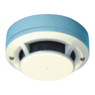
TC846A1005
Intelligent Laser Smoke Sensor
SPECIFICATIONS
Operating Voltage Range:
Standby Current:
Max. Alarm Current (LED on):
Operating Humidity Range:
Operating Temperature Range:
Height:
Diameter:
Weight:
Before installing sensors, please thoroughly read the System Smoke Detector
Application Guide, which provides detailed information on sensor spacing,
placement, zoning, and special applications. Copies of this manual are avail-
able from Honeywell.
NOTICE: This manual should be left with the owner/user of this equipment.
IMPORTANT: This sensor must be tested and maintained regularly following
NFPA requirements. It should be cleaned at least once a year.
GENERAL DESCRIPTION
Model TC846A1005 is a plug-in type smoke sensor that uses a laser based
sensing chamber. The sensor uses analog-addressable communications to
transmit smoke density and other information to the control panel. Rotary-de-
cade switches are provided for setting the sensor's address. Two LEDs on the
sensor are controlled by the panel to indicate sensor status. An output is pro-
vided for connection to an optional remote LED annunciator (P/N RA400Z/
RA100Z).
The TC846A1005 requires compatible addressable communications to
function properly. Connect these sensors to listed-compatible control pan-
els only.
SPACING
Honeywell recommends spacing sensors in compliance with NFPA 72. In low
air flow applications with smooth ceilings, space sensors 30 feet apart. For
specific information regarding sensor spacing, placement, and special applica-
tions, refer to NFPA 72.
Wiring INSTRUCTIONS
All wiring must be installed in compliance with the National Electrical Code,
applicable local codes, and any special requirements of the Authority Having
Jurisdiction. Proper wire gauges should be used. The installation wires should
be color-coded to limit wiring mistakes and ease system troubleshooting. Im-
proper connections will prevent a system from responding properly in the
event of a fire.
REMOVE POWER FROM THE COMMUNICATION LINE BEFORE INSTALL-
ING SENSORS.
All wiring must conform to applicable local codes, ordinances, and regula-
tions.
1.
Wire the sensor base (supplied separately) per the wiring diagram, see
Figure 1.
2.
Set the desired address on the sensor address switches, see Figure 2.
3.
Install the sensor into the sensor base. Push the sensor into the base
while turning it clockwise to secure it in place.
4.
After all sensors have been installed, apply power to the control unit and
activate the communication line.
5.
Test the sensor(s) as described in the TESTING section of this manual.
15 to 32 VDC
330µA @ 24 VDC (one communication every 5 sec. with LED blink enabled)
6.5 mA @ 24 VDC
10% to 93% Relative Humidity, noncondensing
0°C to 38°C (32°F to 100°F); U.S.
–10°C to 50°C (14°F to 122°F); Europe
1.7 inches (43 mm) installed in B210LP Base
6.1 inches (155 mm) installed in B210LP Base
4.1 inches (104 mm) installed in B501 Base
5.0 oz. (142 g)
Dust covers provide limited protection against airborne dust particles during
shipping. Dust covers must be removed before the sensors can sense smoke.
Remove sensors prior to heavy remodeling or construction.
TESTING
Before testing, notify the proper authorities that the system is undergoing
maintenance, and will temporarily be out of service. Disable the system to
prevent unwanted alarms.
All sensors must be tested after installation and periodically thereafter. Test-
ing methods must satisfy the Authority Having Jurisdiction (AHJ). Sensors
offer maximum performance when tested and maintained in compliance with
NFPA 72.
The sensor can be tested in the following ways:
A. FUNCTIONAL: MAGNET TEST (P/N M02-04-01 OR M02-09-00)
This sensor can be functionally tested with a test magnet. The test magnet
electronically simulates smoke in the sensing chamber, testing the sensor elec-
tronics and connections to the control panel.
1.
Hold the test magnet in the magnet test area as shown in Figure 3.
2.
The sensor should alarm the panel.
Two LEDs on the sensor are controlled by the panel to indicate sensor status.
Coded signals, transmitted from the panel, can cause the LEDs to blink, latch
on, or latch off. Refer to the control panel technical documentation for sensor
LED status operation and expected delay to alarm.
B. SMOKE ENTRY: AEROSOL GENERATOR (GEMINI 501)
The GEMINI model 501 aerosol generator can be used for smoke entry testing.
Set the generator to represent 4%/ft. to 5%/ft. obstruction as described in the
GEMINI 501 manual. Using the bowl shaped applicator, apply aerosol until
the panel alarms.
A sensor that fails any of these tests should be cleaned as described under
Cleaning, and retested. If the sensor fails after cleaning, it must be replaced
and returned for repair.
When testing is complete, restore the system to normal operation and notify
the proper authorities that the system is back in operation.
1
1985 Douglas Drive North
Golden Valley, MN 55422 USA
customer.honeywell.com
Honeywell Control Systems Ltd
Honeywell House, Arlington Business Park
Bracknell, Berkshire RG12 1EB UK
CAUTION
I56-0060-007
10-03
Advertisement
Table of Contents

Related Manuals for Honeywell TC846A1005


Summary of Contents for Honeywell TC846A1005
- Page 1 Disable the system to GENERAL DESCRIPTION prevent unwanted alarms. Model TC846A1005 is a plug-in type smoke sensor that uses a laser based sensing chamber. The sensor uses analog-addressable communications to All sensors must be tested after installation and periodically thereafter. Test- transmit smoke density and other information to the control panel.
- Page 2 FIGURE 1. WIRING DIAGRAM CAUTION Do not loop wire under terminal 1 or 2. Break wire run to provide supervision of connection. CAUTION: DO NOT LOOP WIRE REMOTE UNDER TERMINAL 1 OR 2. ANNUNCIATOR BREAK WIRE RUN TO PROVIDE SUPERVISION OF CONNECTIONS. (–) (–) CLASS A OPTIONAL WIRING...
- Page 3 FIGURE 2. ROTARY DECADE ADDRESS SWITCHES TENS ONES C0146-00 FIGURE 3. TEST MAGNET POSITION PAINTED SURFACE LED STATUS MAGNET TEST INDICATORS MARKER C0169-00 TEST MAGNET FIGURE 4. SENSOR ASSEMBLY PAINTED SURFACE SENSOR COVER COVER REMOVAL TABS SCREEN ASSEMBLY SENSING CHAMBER C0170-00 I56-0060-007 10-03...
- Page 4 (one communication every five seconds with LED enabled) GENERAL FIGURE 5. TYPICAL WIRING FROM TC846A1005 TO XLS1000. The TC846A1005 Pinnacle™ Laser Smoke Detector can be used with the Hon- eywell XLS1000 fire alarm control panel. The TC846A1005 is configured in TC846A1005 the SDU data file from the TC846 tab in the 3-AADC configuration screen.
Need help?
Do you have a question about the TC846A1005 and is the answer not in the manual?
Questions and answers