Table of Contents
Advertisement
Advertisement
Table of Contents

Subscribe to Our Youtube Channel
Related Manuals for Lumel PD14


Summary of Contents for Lumel PD14
- Page 1 PROGRAMMER WITH A USB LINK PD14 USER’S MANUAL...
-
Page 3: Table Of Contents
4.1. Basic requirements, operational safety ......6 4.2. Assembling the programmer..........8 4.3. Installing COM port drivers in the komputer ..... 8 4.4. Installing the software of the PD14 programmer ....9 5. DESCRIPTION OF THE PD11 PROGRAM (adapted for PD14) ..............9 5.1. -
Page 5: Application
1. APPLICATION The PD14 programmer with USB link is destined to program transducers of P11 and P12 series and readout archived parameters in the P12 transducers, in the windows 95/98/2000/NT/XP environment. The software applied in PD14 (PD11 programmer) enables: – modification of transducer work parameters, –... -
Page 6: Programmer Installation
In the security scope the programmer meets the requirements of the EN 61010 -1 standard. Remarks concerning the operator safety: 1. G eneral The PD14 programmers are destined to be mounted in accordance with customer’s requirements. Non-authorized removal of the required housing, inappropriate use, ... - Page 7 3. I nsTallaTIon The PD14 programmer must be installed according to the regulation and instructions given in this User’s Manual. Ensure proper handling and avoid mechanical stress. Do not bend any components and do not change any insulation ...
-
Page 8: Assembling The Programmer
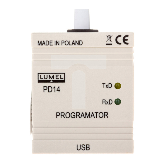
4. 2. Assembling the programmer The programmer is a portable device supplied from the USB bus and transducer. The drawing with overall dimensions of the PD14 programmer is presented on the fig. 1 To the programmer To the computer USB port Fig. -
Page 9: Installing The Software Of The Pd14 Programmer
USB serial transducer, and the Port(Com) - USB Serial Port will be assigned to it. 4.4. Installing the software of the PD14 programmer The PD14 programmer co-operates with the software of the PD14 programmer. In order to install the programmer software under Windows, one must: 1. - Page 10 The program main window is shown on the Fig. 2 Menu Tool Service Transducer Transducer Program features selection status parameters Transducer parameters Fig. 2. The main program windows...
-
Page 11: Menu Bar
5.1 Menu bar The File menu makes available the save of transducer parameters into the file, their read-out and printout. Save parameters..displays the standard save file dialogue, enabling the storage of currently chosen parameters. Load parameters..displays the standard open file dialogue, enabling the read-out of currently chosen transducer parameters. -
Page 12: Toolbar
The Language menu enables the choose of the program language version. The chosen language is marked by The Help menu displays information about the PD11 program version and the producer address. 5.2. Tool bar Read-out Saving Printout Program Exit of parameters of parameters of parameters... - Page 13 Fig. 4 Dialogue window of the access password In case of a correct password, after pressing the „Next >>” key the dialogue (fig.5) will be displayed. A wrong password causes the display of the error message: „Password unconformed with the password in the transducer. Try again.”...
-
Page 14: Field - Transducer Properties
5.5. Field - transducer properties Information concerning the connected transducer is displayed in the field of properties. Program working mode Type of the connected transducer Transducer number Kind of analogue output Program wersion in the transducer Fig. 6. Properties of the transducer - defines the kind of program work. -
Page 15: Field - Service Parameters
5.6. Field - Service parameters Service parameters are presented on the fig. 7. 5 keys are accessible in the service parameter field: - factory settings, - apply parameters - active in the programming mode, - active in the programming mode, - read parameters - change password - active in the programming mode, - unlock password. - Page 16 The read-out and the entry of parameters into the transducer are signalled in the progress window. Fig.8. Progress window during the data transmission. The change of password in the transducer - (active in the programming mode only) enables the change of the password in the transducer (fig. 9.) In order to change the password it is necessary to give the old password (the same which was given in the moment of connection to the transducer), and give the new password together with its renewed confirmation.
- Page 17 Fig.10. Window of password unlocking In order to obtain the unlocking code one should contact the LUMEL’s Export Department (tel./fax (48-68) 325 49 91). When an incorrect unlocking password was given, the following message „Bad unlock code”...
-
Page 18: Transducer Parameters
5.7 Field - Transducer parameters It serves to change transducer parameters, choose the transducer type and move between parameter groups. Transducer Alarm Output Process Recording parameters parameters parameters parameters parameters Fig.11. Transducer parameters 5.7.1. Input parameters They enable the change of the measured quantity, the averaging time of measurements, the decimal point. -
Page 19: Alarm Parameters
Individual characteristic Fig. 12 Input parameters 5.7.2. Alarm parameters Parameters of Alarm 1 and Alarm 2 are identical and occur in P12 series transducer only. They enable to define the alarm type, the lower threshold and the upper threshold, the time-lag of the alarm activation and the maintenance of the alarm signalling after its retreat. -
Page 20: Output Parameters
5.7.3. Output parameters They enable the configuration of the characteristic of the analogue output. It is also possible to configure parameters of the RS-485 interface but only in P12 series transducers Fig. 14. Output parameters 5.7.4. Process parameters They make available the read-out of measured, minimal and maximal values for the input value, the read-out of the current time in the transducer and the percentage value of the analogue output steering-out The read-out of process parameters takes place through the pressure of the... -
Page 21: Recording Parameters
Additionally the possibility to reset the minimal and maximal value is also made available. 5.7.5. Registration parameters They serve to set the date and hour of the registration beginning, its interval and enable the read-out of registered values. CAUTION ! The date of the registration start is an informing parameter. -
Page 22: Technical Data
6. TECHNICAL DATA Galvanic isolation 3000 V d.c. Operation rated conditions: - supply voltage from the transducer and USB port - ambient temperature - 20...23...60°C - storage temperature - 20...+ 70°C - air relative humidity < 95% (condensation inadmissible) - work position Communication parameters: - baud rate 9600 bit/s... - Page 23 „Cannot con- The communication with 1. Check whether the transducer is nected to the the transducer was lost. connected to the network and the transducer - programmer conductor has not The transducer been taken out. does not reply” Caution: The pulling out and the re- newed insertion of the programmer conductor requires the switching off and the renewed transition into the...
-
Page 24: Maintenance And Guaranty
8. MAINTENANCE AND GUARANTY The PD14 programmer does not require any periodical maintenance. In case of some incorrect operations: 1. After the dispatch date and in the period stated in the guaranty card One should return the instrument to the Manufacturer’s Quality Inspection Dept. - Page 28 LUMEL S.A. ul. Sulechowska 1, 65-127 Zielona Góra, POLAND tel.: +48 68 45 75 100, fax +48 68 45 75 508 www.lumel.com.pl Export department: tel.: (+48 68) 45 75 139, 45 75 233, 45 75 321, 45 75 386 fax.: (+48 68) 32 54 091...
Need help?
Do you have a question about the PD14 and is the answer not in the manual?
Questions and answers