Table of Contents
Advertisement
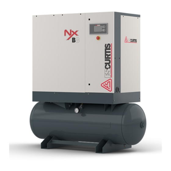
NxB/V
OIL-INJECTED ROTARY SCREW COMPRESSORS
Operator Manual
4 – 15 kW
WARNING
Personal injury and/or equipment damage will be result by failing to pay attention to the vital safety information and instructions
in this manual. Carefully read, understand, and retain all safety information and instructions before operating this compressor.
Series
CAP-834
MAY, 2018
Rev. E
Advertisement
Table of Contents

Subscribe to Our Youtube Channel
Related Manuals for FScurtis NxB/V Series


Summary of Contents for FScurtis NxB/V Series
- Page 1 CAP-834 MAY, 2018 Rev. E NxB/V Series OIL-INJECTED ROTARY SCREW COMPRESSORS Operator Manual 4 – 15 kW WARNING Personal injury and/or equipment damage will be result by failing to pay attention to the vital safety information and instructions in this manual. Carefully read, understand, and retain all safety information and instructions before operating this compressor.
- Page 3 Limitation of liability Information on these operating instructions All information and instructions in this manual have These instructions enable you to use the machine been compiled taking account of the applicable safely and efficiently. The instructions are a compo- standards and regulations, state-of-the-art technol- nent part of the machine and must be accessible for ogy and our years of knowledge and experience.
-
Page 4: Table Of Contents
Table of contents Design and function ..........................7 Overview ............................7 Brief description ..........................9 Assembly description ........................9 1.3.1 Controller ........................... 9 1.3.2 Enclosure panels ........................9 1.3.3 Drive unit ........................... 9 1.3.4 Intake filter ..........................10 1.3.5 Compressor airend ........................10 1.3.6 Oil separator tank ........................11 1.3.7... - Page 5 Table of contents Storage ............................23 Installation and commissioning ......................24 Safety instructions for the installation and commissioning ............24 Requirements in the installation location ..................25 Installation ............................ 25 5.3.1 Remove shipping spacers ...................... 25 5.3.2 Ventilation ..........................25 5.3.3 Connection to the compressed air network ................
- Page 6 Table of contents Commissioning after remedied fault .....................48 Index ..............................49 Appendix ...............................51 10.1 Bolt tightening torque requirements .....................51 CAP-834...
-
Page 7: Design And Function
Design and function 1 Design and function Overview Screw compressor Fig. 1: Standard screw compressor with belt drive 3 - 15 kW) Controller Electrical cabinet Emergency stop button Enclosure panels This chapter shows the screw compressors described in these instructions. They mainly differ in their construc- tion, with or without receiver, and with the attachment of an additional section in which the refrigeration dryer and the frequency converter are installed. - Page 8 Design and function Components The basic construction is the same for all screw compressor variants. The position or look of the assemblies may vary from the illustration Fig. 2: Overview of the assemblies: Screw compressor with frequency converter, refrigeration dryer (optional) and air receiver (optional) Pressure gauge 10 Separator tank...
-
Page 9: Brief Description
Design and function Brief description Enclosure panels 1.3.2 The fresh air supplied by the cooling air fan is fil- tered through the intake filter. The air flows through the intake valve into the compressor airend, where it is compressed together with the injected oil to the final pressure. -
Page 10: Intake Filter
Design and function Compressor airend Screw compressor withV-belt drive and 1.3.5 frequency converter Fig. 7: Compressor airend The air is compressed by the compressor airend (Fig. 7/1) and fed to the oil separator tank (Fig. 7/2) together with the injected oil. The compressor airend and the oil separator tank are enclosed in the same housing. -
Page 11: Oil Separator Tank
Design and function Oil separator tank Air/oil separator 1.3.6 1.3.7 Fig. 10: Air/oil separator The air/oil separator (Fig. 10/1) removes the residu- Fig. 8: Oil separator tank al oil from the compressed air. Oil separator Sight glass Minimum pressure and non- 1.3.8 Filler nozzle return valve... -
Page 12: Coolers
Design and function Coolers Cooling air fan 1.3.9 1.3.11 Fig. 12: Coolers The compressed air is cooled in the air after-cooler (Fig. 12/1) before it leaves the screw compressor via the discharge port (Fig. 12/1). The oil is cooled by the oil cooler (Fig. 12/2) and fed back into the oil circuit. -
Page 13: Refrigeration Dryer
Design and function Refrigeration dryer Interfaces 1.3.12 Air supply Fig. 15: Refrigeration dryer The refrigeration dryer (Fig. 15/1) dries the com- pressed air using a heat exchange process. The compressed air is fed from the oil separator tank into the refrigeration dryer and then directed into the compressed air network via the compressed air port. -
Page 14: Safety
Safety 2 Safety This section is a summary of important safety as- pects to ensure optimum protection of the personnel CAUTION! and safe and trouble-free operation. This combination of symbol and signal word indicates a possibly hazardous The owner, lessor or operator of this com- situation which may cause minor or pressor is hereby notified and forewarned that light injuries if not avoided. -
Page 15: Proper Use
Safety Proper use Warning – high-voltage. The machine is designed and constructed exclu- sively for the proper use described here. Warning – explosive substances. The screw compressor serves exclusively to gener- ate compressed air in an environment not subject to explosion. -
Page 16: General Safety
Safety General safety Safety devices 1. Read and understand all the instructions found in this manual before operating your compressor. WARNING! 2. Disconnect the main power source before Danger to life from nonfunctional working on or performing any maintenance safety devices! procedures on this unit. -
Page 17: Description Of The Installed Safety Devices
Safety Description of the installed Do not change the pressure setting of the pres- 2.4.2 sure relief valve, restrict the function of the re- safety devices lief valve or replace the relief valve with a plug. Emergency stop button Environmental protection NOTICE! Danger to the environment from incorrect handling of pollutants! -
Page 18: Instructions On The Machine
Safety Instructions on the machine Hazardous Voltage WARNING! Danger injury from illegible symbols! Stickers and signs can become dirty or otherwise obscured over time, with the result that dangers cannot be recognized and the necessary operating instructions cannot be complied with. This, in turn, poses a risk of injury. - Page 19 Safety Brief instructions for operation This sticker is on the enclosure and contains brief instructions for operation. CAP-834...
-
Page 20: Technical Data
Technical data 3 Technical data For more information refer to the technical data sheet. Serial tag Fig. 20: Serial tag The serial tag can be found on the enclosure. It includes the following details: 1. Manufacturer 2. Part number 3. Serial number 4. -
Page 21: General Specifications
Technical data General specifications Operating conditions 3.2.1 Environment Data Value Temperature range +37 to +113F (+3 to +45°C) Relative humidity, maximum Maximum installation altitude above sea level 3281ft (1000m) 3.2.2 The following oils have been tested and approved for use in these compressors: Designation Type Synthetic oil... -
Page 22: Transportation, Packaging And Storage
Transportation, packaging and storage 4 Transportation, packaging and storage Safety instructions for Packaging transportation About the packaging The individual screw compressors are packaged in Improper transport cartons or sometimes on wooden frames and ac- cording to the anticipated transport conditions. Only NOTICE! environmentally-friendly materials are used for the Damage to property due to improper... -
Page 23: Transportation
Transportation, packaging and storage Fragile 1. Drive the fork lift with the forks as shown in Fig. 21. 2. Insert the forks so that they stick out on the oth- er side. 3. Ensure that the package cannot tip if the centre Marks packages with fragile or sensitive contents. -
Page 24: Installation And Commissioning
Installation and commissioning 5 Installation and commissioning Safety instructions for the there is a danger of serious injuries or death for persons in the danger zone. installation and commissioning Switch off all power supplies before Electrical system starting work and make sure they cannot be switched on again. -
Page 25: Requirements In The Installation Location
Installation and commissioning Requirements in the installation location Set up the screw compressor so that the following conditions are fulfilled: The installation location is level. ◼ The machine is easily accessible and can be accessed from ◼ all sides. There is sufficient lighting. ◼... -
Page 26: Connection To The Compressed Air Network
Installation and commissioning NOTICE! Risk of material damage from condensation! Cooling air with moisture content can cause condensation. Make sure that the cooling air is cool, dry and free of dust. 1. Provide the required rate of cooling air as per the technical data for the screw compressor Chapter 3 ‘Technical data’... -
Page 27: Connecting To The Power Supply
Installation and commissioning Connecting to the power supply 5.3.4 the compressed air hose with high force. Personnel: Qualified Electrician ◼ Anchor and fasten the compressed air hose sufficiently. NOTICE! Property damage to the compressor airend due to incorrect connection The prerequisite for the correct of the power supply! installation is the presence of a In case of incorrect connection of the... -
Page 28: Checking The Oil Level
Installation and commissioning Checking the oil level 1. Switch the screw compressor off and secure it to prevent it from being switched back on again. 2. Open and remove the enclosure panels with the special wrench. Fig. 26: Intake valve fastening screw 1. -
Page 29: Switching On After Installation
Installation and commissioning Switching on after installation CAUTION! Danger of injury from oil vapor! 1. Check all connections to make sure they are in- In case of high temperatures oil vapor stalled correctly and all screws are properly can form. Oil vapor can irritate eyes fastened. -
Page 30: Setting Parameters
Installation and commissioning 9. Check the compressor temperature NOTICE! Chapter 7.4.5 ‘Checking the compressor Risk of material damage due to too temperature’ on page 39. low or too high compressor temperature! Setting parameters If the compressor temperature is too low or too high, the screw compressor may become damaged. -
Page 31: Operation
Operation 6 Operation Safety instructions for operation Improper operation WARNING! Danger of injury due to improper operation! Improper operation can cause serious injury and significant material damage. Carry out all operating steps in accordance with the information and notices in this manual. Pay attention to the following points before starting work: Ensure that all covers and safety... -
Page 32: Maintenance
Maintenance 7 Maintenance Safety instructions for maintenance, there is a danger of serious injuries or death for persons in maintenance the danger zone. Electrical system Switch off all power supplies before starting work and make sure they DANGER! cannot be switched on again. Use a Danger to life from electric power! lock out and tag out process. - Page 33 Maintenance cloth or Kraft paper. components under pressure, make sure the pressure is relieved. Do not use flammable solvents for cleaning parts Have faulty components that are under pressure during operation When reinstalling previously replaced by appropriate specialist removed components, make sure personnel immediately.
-
Page 34: Spare Parts
Maintenance Environmental protection Observe the following environmental protection Loss of warranty instructions during maintenance work: The use of non-approved In respect of all lubrication points supplied ◼ spare/replacement parts will invalidate manually with lubricant, remove any escaping, the warranty. used or surplus grease and dispose of in accordance with applicable local, state and Procure replacement parts from authorized dealers federal regulations. - Page 35 Maintenance Nx (4-15kW) MAINTENANCE SCHEDULE* SERVICE INTERVALS (HOURS) PART DESCRIPTION Check sump oil level (fill if necessary) Check pressure operat- ing point and controls Check oil scavenger line for oil flow Drain condensate from air receiver Check pressure relief valve for operation Drain condensate from...
-
Page 36: Maintenance Work
Maintenance SERVICE INTERVALS (HOURS) DESCRIPTION PART# FSK-26NX4- 2000/ 6000 Hour Service FSK-26NX8- FSK-4NX4-6 4000 Hour FSK-4NX8- Service Kit FSK-8NX4-6 8000 Hour Service FSK-8NX15- Change Lubricant FSC-8000 ... -
Page 37: Checking For Leaks
Maintenance discharged. Necessary maintenance work Necessary maintenance work appears on the display of the controller as a 1. Close the shut-off valve on the pressure network warning Controller documentation. side and secure it to prevent it from being opened again. Observe all safety instructions and precautions as 2. -
Page 38: Checking The Build-Up Of Condensation
Maintenance Topping up the oil Fig. 30: Filler pluge Fig. 29: Filler plug 5. Use a funnel (Fig. 30/1) to top up the oil to the filling edge on the filler plug (Fig. 30/3). 1. Close the shut-off valve on the pressure network side and secure it to prevent it from being 6. -
Page 39: Checking The Compressor Temperature
Maintenance Checking the compressor 1. Close the shut-off valve on the pressure network 7.4.5 side and secure it to prevent it from being temperature opened again. 2. Open and remove the enclosure panels with the special wrench. NOTICE! 3. Use a drip pan to make sure that the leaking oil Property damage due to compressor is collected. -
Page 40: Checking The Drive Unit
Maintenance out of rather than into the machine. In case of severe dirt buildup, consult the manufacturer. Checking the drive unit 7.4.7 1. Close the shut-off valve on the pressure network Fig. 33: Oil drain side and secure it to prevent it from being opened again. -
Page 41: Replacing The Air/Oil Separator
Maintenance 10. Switch on the compressor and switch it off The oil is drained. again without waiting any longer than one mi- 6. Close the oil drain (Fig. 36/1). nute controller documentation. 11. Check the oil level and top up as necessary Chapter 7.4.3 ‘Checking the oil level/topping ... -
Page 42: Replacing The Intake Filter
Maintenance Replacing the intake filter 7.4.10 Standard intake filter 1. Close the shut-off valve on the pressure network side and secure it to prevent it from being opened again. 2. Open and remove the enclosure panels with the special wrench. Fig. -
Page 43: Measures After Maintenance Has Been Performed
Maintenance shut-off valve. Measures after maintenance has been performed 4. Clean the work area and remove any substanc- es such as liquids, processing material or similar After completion of the maintenance work and be- that may have escaped. fore switching the machine on, carry out the follow- 5. -
Page 44: Faults
Faults 8 Faults The following section describes possible causes of Improperly executed troubleshooting work faults and the work to remedy them. In case of faults that occur more than once, shorten WARNING! the maintenance intervals according to the actual Danger of injury from improper utilization. -
Page 45: Fault Displays
Faults Oil vapor during all work hear hot surfaces. Before all work, make sure that all CAUTION! surfaces have cooled off to the Danger of injury from oil vapor! ambient temperature, wait at least In case of high temperatures oil vapor 30 minutes. -
Page 46: Fault Table
Faults Fault table Fault description Cause Remedy Compressor tem- Intake or ambient tempera- Ventilate compressor room perature too high ture too high Cooling air intake or outlet Unblock cooling air intake or outlet sufficiently blocked Oil is soiled Change oil ... - Page 47 Faults Fault description Cause Remedy Screw compressor Network pressure set too high Reset network pressure Controller documentation does not start au- Interruption in the power cir- Check power circuit for interruption tomatically or does cuit not discharge after previous switching- Ambient temperature below Install additional heating or temper compressor room off by reaching the...
-
Page 48: Work For Fault Clearance
Faults Work for fault clearance 6. Clean the return line (Fig. 41/1) and nozzle. If necessary, replace them with original spare Clean/replace return line parts ( Parts List). 1. Switch the screw compressor off and secure it to 7. Place the nozzle and return line (Fig. 41/1) back prevent it from being switched back on again. -
Page 49: Index
Index 9 Index Description of function ..........9 Air/oil separator ............11 Drive unit ..............9 Assemblies Dryer ..............13 Air/oil separator ..........11 Compressed air after-cooler ......12 Compressor airend ..........10 Emergency stop button ......... 17 Cooler ..............12 Environmental protection Cooling air fan ............ - Page 50 Index Checking the oil level ......... 37 Relief valves ............17 Oil change ............40 Replacing the intake filter ........42 Replacing the intake filter ........42 Replacing the oil ..........40 Safety ..............14 Replacing the oil filter ......... 40 Safety devices ............
-
Page 51: Appendix
Appendix 10 Appendix Bolt tightening torque requirements 10.1 Lock screw/nuts B 158/193/196/251 design or similar Thread Category 8.8 Unit Category 10.9 Unit 3.69 (5) lbf ft (Nm) 7.38 (10) lbf ft (Nm) 5.9 (8) lbf ft (Nm) 13.28 (18) lbf ft (Nm) 14.75 (20) lbf ft (Nm) 32.45 (44)
Need help?
Do you have a question about the NxB/V Series and is the answer not in the manual?
Questions and answers