
Subscribe to Our Youtube Channel
Related Manuals for Balluff BNI PNT-104-105-Z015


Summary of Contents for Balluff BNI PNT-104-105-Z015
- Page 1 BNI PNT-104-105-Z015 BNI PNT-202-105-Z015 BNI PNT-206-105-Z015 BNI PNT-302-105-Z015 BNI PNT-305-105-Z015 IP67 Modules User’s Guide...
-
Page 2: Table Of Contents
Hardware configuration Device name, Profinet address Establishing device relationship Assigning device name Concluding the configuration 5.2. Functions in module properties Module settings Port functions Safe state 5.3. Bit mapping and function Inputs pin 4 Inputs pin 2 Outputs pin 4 www.balluff.com... -
Page 3: Inputs Pin
6.6. Channel Error Type Webserver 7.1. General Information 7.2. Navigation / Info 7.3. Login/Logout 7.4. "Home" dialog 7.5. "Config" dialog 7.6. "Log" dialog Monitoring & Diagnostics 8.1. General 8.2. SNMP MIBs Appendix 9.1. Included material 9.2. Order code 9.3. Order Information Notes www.balluff.com... -
Page 4: Notes
Balluff Network Interface Profinet Notes 1.1. Structure of the The guide is organized so that the chapters build on one another guide Chapter 2: Basic safety information Chapter 3: Getting started Chapter 4: Technical data …. 1.2. Typographical The following typographical conventions are used in this Guide. -
Page 5: Safety
Attention! voltage Disconnect all power before servicing equipment. Note In the interest of product improvement, the Balluff GmbH reserves the right to change the specifications of the product and the contents of this manual at any time without notice. www.balluff.com... -
Page 6: Getting Started
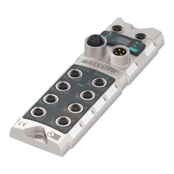
Balluff Network Interface Profinet Getting Started 3.1. Module overview Figure 1 – Overview BNI PNT-xxx-105-Z015 Mounting hole Port 6 PROFINET ™ port 2 Port 4 Display Port 2 Power Supply In Port 0 Status LED: Communication / Module Power Supply Out... -
Page 7: Mechanical Connection
PROFINET M12, D-coded, female Interface Function Transmit Data + Receive Data + Transmit Data - Receive Data - Note Unused I/O port socket must be fitted with cover caps to ensure IP67 protection rating. www.balluff.com... -
Page 8: I/O-Port
Balluff Network Interface Profinet Getting Started I/O-Port Function Input/Output Output Input +24V, 200mA* +24V, 200mA +24V, 200mA n.c. Output 2A* Input / Output 2A Input n.c. Input / Output 2A Output 2A Input * Only for BNI PNT-206-105-Z015 Note For the digital sensor inputs follow the input guideline per EN61131-2, type 2. -
Page 9: Technical Data
Approx. 670 gr. 4.3. Operating Operating temperature T -5 °C ... 70 °C conditions Storage temperature -25 C ... 70 °C 4.4. Electrical data Supply voltage 18...30.2 V DC, per EN 61131-2 Ripple <1% No-load current at 24 V 130 mA www.balluff.com... -
Page 10: Profinet
Balluff Network Interface Profinet Technical data 4.5. PROFINET PROFINET port 1 x 10Base-/100Base-Tx Connection for PROFINET port M12, D-coded Cable types per IEEE 802.3 Shielded twisted pair min. STP CAT 5/ STP CAT 5e Data transmission rate 10/100 Mbit/s Max. cable length... -
Page 11: Integration
The device data required for project planning is saved in GSDML files (Generic Station Description Markup Language). The GSDML files are available in two languages as an Internet download (www.balluff.com). The data modules of an IO-Link block are displayed in the project planning software according to the slot. -
Page 12: Configuration Of The Header Module
Balluff Network Interface Profinet Integration Configuration of Double-click on the header module to open its properties. the header Click on the "Parameter" tab to open a menu selection for defining the port functions and module diagnostic functions. Note Standard input and output: For each port, the function (N.C., N.O., diagnostic input (pin 2)) can be arbitrarily... -
Page 13: Hardware Configuration
To address the inputs and outputs, input pin 2 / 4 and output 2 / 4 must be taken over from the catalog and used in the configuration according to the given modules. With the remaining modules, the various functions are mapped into the process data areas. www.balluff.com... -
Page 14: Device Name, Profinet Address
Balluff Network Interface Profinet Integration Device name, Double-click on the module in the Profinet line to view the communication parameters of the Profinet address module. The device name and the Profinet address (IP) are configured here. www.balluff.com... -
Page 15: Establishing Device Relationship
Select the desired name and use "Assign name" to assign the marked device that you name found. The device name must be the same as that previously configured under device properties (see previous page) Identification takes place via the MAC address (on the rear of the device) or via the Blink Test. www.balluff.com... -
Page 16: Concluding The Configuration
Balluff Network Interface Profinet Integration Concluding the Download the configuration into HW config. configuration At this point, the bus error on the module should disappear. If the module still reports a bus error, there could be a problem in one of the following areas: Device relationship not established. -
Page 17: Bit Mapping And Function
If this function is configured, after an actuator short-circuit there is no automatic restart, but rather the port must be activated by inserting the corresponding bit. Bit 7 Bit 6 Bit 5 Bit 4 Bit 3 Bit 2 Bit 1 Bit 0 www.balluff.com... -
Page 18: Peripheral Error, Socket
Balluff Network Interface Profinet Integration Peripheral error, Feedback indicating the port at which an error occurred. socket Bit 7 Bit 6 Bit 5 Bit 4 Bit 3 Bit 2 Bit 1 Bit 0 Short-circuit Feedback indicating the port at which there is a sensor supply short circuit. -
Page 19: Diagnostics
Block Header, Alarm Specifier, Channel Properties Byte Value Meaning Block Block Type Block Length Block Version High Block Version Low Alarm type Block Header Slot number Subslot number Module ID Submodule ID AlarmSpecifier User Structure ID AlarmSpecifier Channel number ChannelProperties ChannelProperties ChannelErrorType www.balluff.com... -
Page 20: Block Header
Balluff Network Interface Profinet Diagnostics 6.2. Block Header The first part of the diagnosis is the so-called Block Header, which is 24 bytes long. Block Type The first 2 bytes of the Block Header are described by the Block Type to define the data type. -
Page 21: Module Id
State Possible values Meaning 0x00 No further diagnosis of module is present At least one further diagnosis of the module is 0x01 present User Structure ID 2 bytes, describes the type of diagnosis Possible values Meaning 0x8000 Channel-related diagnosis www.balluff.com... -
Page 22: Channel Number
Balluff Network Interface Profinet Diagnostics 6.4. Channel Number Configuration as standard I/O Error Type Channel Number Undervoltage US 8000 Undervoltage UA 8000 No UA 8000 0…..n Sensor Short circuit Pin 1 - 3 0…..n Actor Short circuit Pin 2 - 3 0…..n... -
Page 23: Specifier
0x0005 Temperature limit exceeded 0x0006 Cable break 0x0007 Upper threshold exceeded 0x0008 Lower threshold undershot 0x0009 Error 0x001A External error 0x001B Sensor has incorrect configuration (IO-Link device) 0x0101 Actuator warning 0x0105 Actuator supply undervoltage 0x0104 No actuator power supply www.balluff.com... -
Page 24: Webserver
Balluff Network Interface Profinet Webserver 7.1. General The BNI fieldbus module contains an integrated web server for retrieving detailed device Information information and for configuring the device. To use the web interface you must first ensure that the module has been correctly integrated into your network. -
Page 25: Navigation / Info
The navigation bar is located in the upper area of the window, which allows you to switch between the various dialogs of the web interface. To do this click on the corresponding icon. When the "Info" tab is selected the following overview appears: The "BALLUFF" logo at upper right links to the international Balluff homepage. www.balluff.com... -
Page 26: Login/Logout
Balluff Network Interface Profinet Webserver 7.3. Login/Logout To make configuration settings on the fieldbus module using the web interface, you must first log in. Functionalities which cannot be used without logging in are indicated by the grayed out buttons. The default password is: "BNIPNT“... -
Page 27: Home" Dialog
You are also shown whether the configuration block was enabled by the controller (PLC). Information is also shown about the current process data and the status of the module via the corresponding LEDs. After selecting "LED Legend" a Help dialog appears which explains the meaning of the LEDs www.balluff.com... - Page 28 Balluff Network Interface Profinet Webserver PNT: EIP: www.balluff.com...
-
Page 29: Config" Dialog
Webserver 7.5. "Config" dialog The configuration page enables configuration of the module. You can change the module information texts and the (for EIP) IP-Configuration. PNT / ECT: www.balluff.com... - Page 30 Balluff Network Interface Profinet Webserver EIP: The parameter set “Module Configuration” on the left side is used by clicking "Save Configuration" and permanently stored in the device. The "Reboot" button reboots the device as if the power to the module had been turned off and on again.
-
Page 31: Log" Dialog
After a reset, reboot or loss of power the time begins to run again from the year 2000. Clicking on "Update Log” refreshes the display, and "Clear Log” deletes all entries. The log entries are stored in a ring buffer. www.balluff.com... -
Page 32: Monitoring & Diagnostics
{1.3.6.1.4.1.44233.1.2.1} For Balluff products with Product enterprise Number (PEN) = 44233, the product list is defined in BALLUFF-PRODUCTS-MIB sysUpTime The time (in hundredths of a second) since the network management portion of the system was last re-initialized. - Page 33 Number of received frames that were rejected as invalid by the IO-Link-Master (Abort). ifOutOctets The total number of octets transmitted out of the interface, including framing characters. ifOutErrors Number of retries by the IO- Link-Master, indicating unsuccessful packet transmissions. www.balluff.com...
-
Page 34: Appendix
Balluff Network Interface Profinet Appendix 9.1. Included material The BNI PNT consists of the following components: Standard I/O Module 4 blind plugs M12 Ground strap Screw M4x6 20 labels 9.2. Order code BNI PNT-xxx-105-Z015 Balluff Network Interface... -
Page 35: Notes
Notes www.balluff.com... - Page 36 Balluff GmbH Schurwaldstrasse 9 73765 Neuhausen a.d.F. Germany Tel. +49 7158 173-0 Fax +49 7158 5010 www.balluff.com balluff@balluff.de...
Need help?
Do you have a question about the BNI PNT-104-105-Z015 and is the answer not in the manual?
Questions and answers