Table of Contents
Advertisement
Advertisement
Table of Contents

Related Manuals for GPI GPR-R9H

Summary of Contents for GPI GPR-R9H
- Page 1 INSTRUCTION MANUAL ROTARY LASER LEVEL...
- Page 3 To help you use this instrument conveniently, we provide a specific operation manual for you. Please read the manual carefully before you use the instrument and keep it well. FOR YOUR RECORD Place Of Purchase : ........Date Of Purchase : ..../.../..
-
Page 4: Table Of Contents
Contents 1. Main body..................- 2 - 2. Directions..................- 6 - 3. Recharge battery ................- 11 - 4. Accuracy Checking............... - 13 - 5. Specifications................. - 15 - 6. Detector ..................- 17 - 7. Remote ................... - 20 - - 1 -... -
Page 5: Main Body
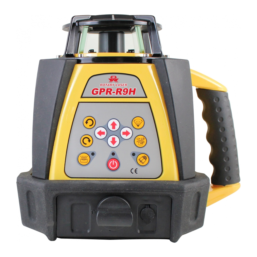
1. Main body Laser window Laser Module Panel Handle Plug hole Battery container - 2 -... - Page 6 1.1 Panel (7) Setting slope (6) Rotating speed (3) Left spinning (3) Right spinning (5) Angle scanning (4) Anti-drift (2) Auto/manual (1) Power ON/OFF - 3 -...
- Page 7 1.2 Operation instrument (1) Power(ON/OFF):Controlling the state of power. (2) Auto/manual: Push button to switch manual Remote or auto leveling. (3) Left / right spinning:After the laser head speed is set on 0 r.p.m. the left/right button can change the laser position. (4) Anti-drift: The Anti-Drift System, when ON, will signal to the operator that the instrument has been moved out of level.
- Page 8 (7) Setting slope (manual mode):The arrow button for upper & down & left & right can adjust X and Y axis.(Touch panel direction is Y axis) - 5 -...
-
Page 9: Directions
2. Directions 2.1. Battery Installment (1) Take down the cover of battery case at the bottom of the instrument. (2) Put the batteries into the case according to the right position. (3) Lay the cover on the box, and then tighten all screws. 2.2 Instrument Placement 2.2.1 Horizontal scanning (manual mode) Lay the instrument on the tripod or stable flat surface, or even hang it on the wall. - Page 10 Lay the instrument on the flat surface, and keep the slope of instrument within the range from -5° to +5°. 2.3 Operations 2.3.1 Power (1) Press the key ON/OFF to bring automatic leveling into function when the power indicator lights. (2) When power indicator blink, it shows the voltage of the batteries is insufficient.
- Page 11 finish leveling. (2) If the instrument is placed improperly, or the slope of instrument exceeds the range from -5° to +5°, the mode indicator and the laser beam will wink at the same time. Then place the instrument properly. 2.3.3 Spinning (1) Change speed Press the rotating speed button to control the spinning speed of the laser head.
- Page 12 then press the key Left-spinning, the laser head will step-move counter-clockwise. 2.3.4 Directional scanning (1) Press the Key Directional scanning: the laser head will scan directionally. If press the key repeatedly, the angle of scanning of laser head will continuously changes as follows: 0, -10°, -45°, -90°, -180°, -0°...
- Page 13 Aim the X1-beam to the direction of the slope required to adjust, as depicted below. Press the key ← or → to move the laser beam up or down. (2) Slope of Y-axis Aim the Y1-beam to the direction of the slope required to adjust. Press the key ↑...
-
Page 14: Recharge Battery
3. Recharge battery (1) When the batteries needs to be charged, connecting the charger with AC. Insert the plug of charger into the plug hole at the bottom of the instrument (As depicted below). (2) If the indicator of charger lights, it shows the batteries are being charged. (3) If the indicator light of the charger winks, it shows the course of recharging has ended. - Page 15 finished within 7 hours. 2. Power required for the charger: Frequency: 50-60HZ; Voltage: 85-265V. 3. Charging and using of the instrument can progress simultaneously. 4. If keeping the instrument in storage (or Leave the instrument unused for a long time), the batteries (dry battery or rechargeable battery) needs to be taken out. 5.
-
Page 16: Accuracy Checking
4. Accuracy Checking 4.1 Horizontal-surface Checking (1) Place the instrument at the point of 50m in front of wall (or set a scale plate at the point of 50m away from the instrument), and then adjust the level of the base approximately to aim the X1 to the wall (or scale plate), as depicted below: X1-beam... - Page 17 (2) After switching on the power, use the laser detector measuring the h1 of X1-beam on the wall or scale plate. (3) Loose the screw of the tripod, and then turn around the instrument 180° to measure the h2 of X2-beam on the wall or scale plate. D-value between h1 and h2 ought to be less than 10mm (4) Check the Y-beam in the same way.
- Page 18 (3) Switch on the power, and then measure the middle point of the laser beam on the wall (or scale plate):hA, hB and hA’ , hB’ 1=hA-hA’ , 2=hB-hB’ D-value between 1 and 2 ought to be less than 6mm 0.5m about 30m about 30m...
-
Page 19: Specifications
5. Specifications Model no. GPR-R9H GPR-G9 Red beam-High power Green beam Light source wavelength 635nm wavelength 532nm Leveling accuracy 10”/ ±20” Self-leveling range 5° Measuring range Diameter: 500m (Using the laser detector) Spinning speed 0,60,120,300,600 r.p.m. Directional-scanning 0°, 10°, 45°, 90°,180°... -
Page 20: Detector
6. Detector LCD readout window The Universal Laser Detector Beam capture aids in locating and targeting a visible or invisible beam emitted by a rotary laser; perfect for use in outdoor conditions, where sunlight and distance may make locating the beam more difficult. Volume ON/OFF The laser detector includes a rod Speaker... - Page 21 6.1 Operation instrument (1) Mount the instrument onto a sighting rod if you are using one. Turn on the instrument by pressing the ON/OFF pad. The LCD symbols will momentarily flash and the “coarse” beam indicator symbol will remain lit and the audio signal will be on.
- Page 22 the most accurate pinpointing of level. (to see the available Resolutions, please refer to the Specs Table). (4) Move the detector upward when the low beam indicator light is lit (with volume on, a short pulsing audio tone is heard). Move the detector downward when the high beam indicator arrow is lit (with volume on, a long pulsing audio tone is heard).
-
Page 23: Remote
7. Remote The remote of the instrument adopts the infrared technique. Aim the aperture of infrared ray to the instrument (as depicted below) to bring remote controlling into function (Available distance: 20M). The tele controlling panel includes 9 keys; the indicator on the device will wink to show the operating signal has been sent out once pressing any key. - Page 24 Memo...
- Page 25 Memo...
- Page 26 Memo...
- Page 28 Giant Precision Instrument Co., Ltd.
Need help?
Do you have a question about the GPR-R9H and is the answer not in the manual?
Questions and answers