
Related Manuals for Huawei SmartAX MA5800-X7


Summary of Contents for Huawei SmartAX MA5800-X7
- Page 1 SmartAX MA5800-X7 Quick Installation Guide Issue: 04 Date: 2016-08-24 HUAWEI TECHNOLOGIES CO., LTD.
- Page 2 About This Document Intended Audience This document describes how to install the MA5800-X7. The intended audience is hardware installation engineers. Symbol Conventions The symbols that may be found in this document are defined as follows. Symbol Description Indicates an imminently hazardous situation which, if not avoided, will result in death or serious injury.
-
Page 3: Table Of Contents
C o n t e n t 1 Precautions …………………………………..…………………………......………….1 2 Tools and Meters………………………….…………………………......…………….2 3 Appearance and Structure………………………………………......…………….3 4 Environment Requirements on Third-Party Cabinets ………………….………4 5 S pace Re qui reme nts on Thi rd -Pa rty Ca bi ne ts ……………… .… …… . . … ..5 5.1 When the Cabinet Accommodates One MA5800-X7 Subrack………….………….5 5.2 When the Cabinet Accommodates One MA5800-X7 Subrack and Another Device..6 6 Installing the Service Subrack……………….…………………….......………...7... -
Page 4: Precautions
• After the identification plate for the power cable is attached to the power cable, the text area of the plate must face rightwards or upwards. Ensure that the side attached with the label faces outwards. Copyright © Huawei Technologies Co., Ltd. 2015 All rights reserved. -
Page 5: Tools And Meters
2 Tools and Meters Before you begin, get the following tools ready. Marker Flat-head screwdriver Phillips screwdriver Diagonal pliers Network cable Network cable tester Multimeter Optical power meter crimping pliers ESD gloves ESD wrist strap Optical fiber Optical fiber cleaner microscope... -
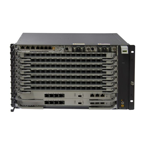
Page 6: Appearance And Structure
3 Appearance and Structure The MA5800-X7 service subrack is 6 U high, and has a fan tray at the right. The subrack is installed in the cabinet through the ETSI or IEC mounting ears. Universal interface board Power board Fan tray Cable Manager Service board Grounding point... -
Page 7: Environment Requirements On Third-Party Cabinets
Huawei for the MA5800-X7. • Cabinet door requirement: When devices are operating, keep the cabinet door closed. • Grounding requirement: Huawei cabinets are grounded through mounting bars. Ensure that third-party cabinets are properly grounded based on site conditions. • Power distribution requirements: Ensure that an over-current protection mechanism has been deployed on the upper-level device. -
Page 8: Pace Re Qui Reme Nts On Thi Rd -Pa Rty Ca Bi Ne Ts
5 Space Requirements on Third-Party Cabinets 5.1 When the Cabinet Accommodates One MA5800-X7 Subrack • The MA5800-X7 supports left-in right-out heat dissipation, so the cabinet must have an unblocked air inlet on its door. • You are advised to reserve more than 4 U space above and under the MA5800-X7 respectively to minimize the impact on other components in the cabinet. -
Page 9: When The Cabinet Accommodates One Ma5800-X7 Subrack And Another Device
5 Space Requirements on Third-Party Cabinets 5.2 When the Cabinet Accommodates One MA5800-X7 Subrack and Another Device • Reserve 10 U space between the devices or add a 3 U air deflector to redirect air flows to minimize the mutual heat dissipation impacts on the devices. •... -
Page 10: Installing The Service Subrack
6 Installing the Service Subrack • The MA5800-X7 service subrack is configured with IEC (19-inch) mounting ears by default. The MA5800-X7 subrack can be mounted in an IEC cabinet or rack. To install the MA5800-X7 subrack in an ETSI cabinet, uninstall the IEC mounting ears, and then install the ETSI (21- inch) mounting ears. -
Page 11: Installing The Service Subrack In An Iec Cabinet
6 Installing the Service Subrack 6.2 Installing the Service Subrack in an IEC Cabinet Install the cable manager on the left Locate the installation side of the service subrack positions of the cable manager and service subrack Cable manager on the mounting bars, and install captive nuts at these positions. -
Page 12: Routing Cables
7 Routing Cables This document describes cable routing using the N63E-22 cabinet as an example. This cable routing also applies for the IEC cabinets (19-inch) or racks. 7.1 Cabinet with Routed Cables (DC) Installation positions for floating nuts Top of the cabinet (top view) Cable hole for fibers, clock cables, network... -
Page 13: Cabinet With Routed Cables (Ac)
7 Routing Cables This section uses cable routing in the N66E-22 cabinet as an example. 7.2 Cabinet with Routed Cables (AC) Floating nuts positions Unit: mm Top view Cable holes Binding plate... -
Page 14: Routing Pgnd Cable And Power Cables
• Before routing the power cable, turn off the output switch of the DC power system. Connect the PGND cable If the subrack is installed in a Huawei cabinet, it does not need to be separately grounded because the Huawei cabinet has been ground through mounting ears. However, it needs to be separately grounded if being installed in a third-party cabinet or rack that cannot be grounded through mounting ears. -
Page 15: Routing Clock Cables
7 Routing Cables 7.4 Routing Clock Cables BITS IN0 to clock source BITS IN1 to clock source BITS OUT to lower level clock Network cable... -
Page 16: Routing Network Cable
7 Routing Cables 7.5 Routing Network Cables TO the maintenance terminal or transmission unit Network cable... -
Page 17: Routing Trunk Cables
7 Routing Cables 7.6 Routing Trunk Cables To DDF Binding position Trunk cable Flat-head screwdriver... -
Page 18: Routing Optical Fibers (P2P Board)
7 Routing Cables 7.7 Routing Optical Fibers (P2P Board) • When handling optical fibers, do not stand close to or look into the optical fiber outlet directly with naked eyes. • Lead the optical fiber through a corrugated pipe. The mouth of the corrugated pipe must be wrapped with the adhesive tape. -
Page 19: Routing Optical Fibers (Pon Board)
7 Routing Cables 7.8 Routing Optical Fibers (GPON Board) • When handling optical fibers, do not stand close to or look into the optical fiber outlet directly with naked eyes. • Lead the optical fiber through a corrugated pipe. The mouth of the corrugated pipe must be wrapped with the adhesive tape. -
Page 20: Routing Optical Fibers (Upstream)
7 Routing Cables 7.9 Routing Optical Fibers (Upstream) • When handling optical fibers, do not stand close to or look into the optical fiber outlet directly with naked eyes. • Lead the optical fiber through a corrugated pipe. The mouth of the corrugated pipe must be wrapped with the adhesive tape. -
Page 21: Post-Installation Check
8 Post-Installation Check Description Method Do not place any materials on the chassis. Observe All vacant slots in a service subrack are filled in with filler panels. Observe All the cables are bound with proper tightness. The space between Observe the cable ties is even, and the remaining parts of the cable ties are cut off neatly. -
Page 22: Power-On Check
9 Powering On the System Power on the device only when the input voltage is in the normal range. • Use the multimeter to test the voltage between NEG(-) and RTN(+) on the DC PDU for the device powered by -48 V DC. The voltage should range from -38.4 V to -57.6 V. •...
Need help?
Do you have a question about the SmartAX MA5800-X7 and is the answer not in the manual?
Questions and answers