Table of Contents
Advertisement
Available languages
Available languages
Manual de Usuario / User's Manual
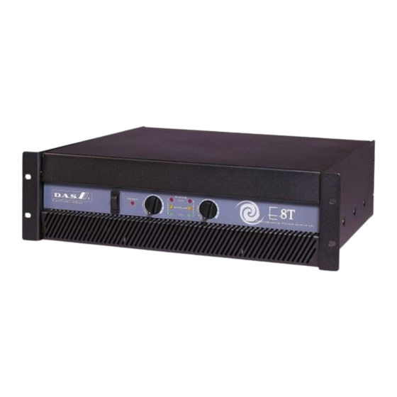
energy series
Antes de utilizar el equipo, lea la sección
"Precauciones de seguridad" de este manual.
Conserve este manual para futuras consultas.
Before operating the device, please read the
"Safety precautions" section of this manual.
Retain this manual for future reference.
Advertisement
Table of Contents

Related Manuals for DAS Energy Series


Summary of Contents for DAS Energy Series
- Page 1 Manual de Usuario / User’s Manual energy series Antes de utilizar el equipo, lea la sección “Precauciones de seguridad” de este manual. Conserve este manual para futuras consultas. Before operating the device, please read the “Safety precautions” section of this manual.
- Page 2 energy...
- Page 3 Precauciones de Seguridad Precauciones de Seguridad Safety Precautions Safety Precautions Amplificadores de Potencia para sistemas distribuidos / Power Amplifiers for distributed systems Amplificadores de Potencia para sistemas distribuidos / Power Amplifiers for distributed systems Conserve y lea todas estas instrucciones.
- Page 4 GARANTÍA Todos nuestros productos están garantizados por un periodo de 24 meses desde la fecha de compra. Las garantías sólo serán válidas si son por un defecto de fabricación y en ningún caso por un uso incorrecto del producto. reparaciones garantía pueden realizadas,...
- Page 5 C/ Islas Baleares, 24 - 46988 - Pol. Fuente del Jarro - Valencia. España (Spain). serie energy Declara que la energy series Declares that Cumple con los objetivos esenciales de las Directivas: Abide by essential objectives relating Directives: Directiva de Baja Tensión (Low Voltage Directive) 2006/95/CE Directiva de Compatibilidad Electromagnética (EMC)
- Page 6 / energy / Manual del Usuario User’s Manual...
- Page 7 ÍNDICE PRESENTACIÓN Generalidades Características DESCRIPCIÓN DEL PANEL FRONTAL Interruptor de encendido Indicadores de encendido Controles de nivel Indicadores de recorte Indicadores de protección Rejillas de ventilación DESCRIPCIÓN DEL PANEL POSTERIOR Salida de línea de altavoces Entradas Conmutador de modo de funcionamiento Cable de red Rejillas de entrada de aire INSTALACIÓN...
- Page 8 / energy / Manual del Usuario User’s Manual...
- Page 9 PRESENTACIÓN B) Indicadores de encendido (POWER e IDLE) Estos LED (verde ‘IDLE’ y rojo ‘Power’) están Generalidades iluminados cuando el amplificador está encendido. Gracias por adquirir un amplificador D.A.S. C) Controles de nivel (LEVEL) Nuestros amplificadores potencia están El volumen (ganancia de entrada) de cada construidos con la más avanzada tecnología canal puede ser ajustado independientemente por modular y han sido diseñados en su totalidad con...
- Page 10 DESCRIPCIÓN DEL PANEL POSTERIOR CAUTION ATTENTION RISK OF ELECTRIC SHOCK DANGER D’ELECTROCUTION SPEAKER DO NOT OPEN NE PAS OUVRIR OUTPUT CHANNEL B CHANNEL A CHANNEL A SIGNAL BRIDGE INPUT 200V 1 2 3 4 5 6 7 8 91 WARNING: TO REDUCE RISK OF FIRE OR ELECTRIC SHOCK DO NOT EXPOSE THIS EQUIPMENT TO RAIN OR MOISTURE CHANNEL B VER MANUAL DE INSTRUCCIONES PARA LA CONEXIÓN...
- Page 11 INSTALACIÓN Montaje Conexión a la red eléctrica Los amplificadores están diseñados para ser La tensión nominal de funcionamiento es 230 montados en un rack estándar de 19 pulgadas. V AC. Las versiones para exportación pueden Su altura es de tres unidades DIN. operar a una tensión nominal de 115V AC.
- Page 12 ESPECIFICACIONES E-8T E-12T MODEL Distributed Output Power Stereo Mode 70 V or 100 V 450 W 650 W Bridge Mono Mode 140 or 200 V 790 W 1220 W Frequency Response 60 Hz-16 kHz +0/-3 dB 60 Hz-16 kHz +0/-3 dB Signal to Noise(20 Hz-20 kHz) -92 dB -92 dB...
- Page 13 APÉNDICE A. Conexiones en modo puente El procedimiento para usar el amplificador en modo puente es el siguiente : 1. Apague el amplificador. 2. Baje al mínimo los dos controles de volumen. (Ambos atenuadores girados totalmente en sentido anti- horario). 3.
- Page 14 APÉNDICE B: Conexiones de línea no-balanceadas y balanceadas Existen dos métodos básicos para transportar la señal de audio con nivel de micrófono o línea: Línea no-balanceada: Emplea un cable con dos conductores, transpor tando la señal como diferencia de potencial (voltaje) entre ambos.
- Page 15 APÉNDICE C. Tablas de emisión de calor y consumo Consumos eléctricos (A) / Power consumtion (A) Modelo / Model Carga / Load Potencia de salida / Output Power Sin señal / Idle E-8T 70 V or 100 V E-12T 70 V or 100 V Emisión de Calor (BTU/h-kcal/h) / Heat Emission (BTU/h-kcal/h) Modelo / Model Carga / Load...
- Page 16 / energy / Manual del Usuario User’s Manual...
-
Page 17: Table Of Contents
CONTENTS INTRODUCTION General Features FRONT PANEL DESCRIPTION Power switch Power LED Input level controls Clip LED Protection LED Cooling air outlet grilles BACK PANEL DESCRIPTION Speaker outputs Inputs Input mode switch Mains LED Fan inlet grilles INSTALLATION Racking Cooling Input cable connections Speaker cable connections Connetion to mains Current draw... - Page 18 / energy / Manual del Usuario User’s Manual...
-
Page 19: Introduction
INTRODUCTION B) Power LEDs (POWER and IDLE) General Thank you for purchasing a D.A.S. power When lit, these LEDs (green ‘IDLE’ and red amplifier. It has been built with the most advanced ‘Power’) show that the amplifier is on. modular technology, and has been designed C) Input LEVEL controls through the use of computer-aided design for both the electronic and mechanical parts. -
Page 20: Back Panel Description
BACK PANEL DESCRIPTION CAUTION ATTENTION RISK OF ELECTRIC SHOCK DANGER D’ELECTROCUTION SPEAKER DO NOT OPEN NE PAS OUVRIR OUTPUT CHANNEL B CHANNEL A CHANNEL A SIGNAL BRIDGE INPUT 200V 1 2 3 4 5 6 7 8 91 WARNING: TO REDUCE RISK OF FIRE OR ELECTRIC SHOCK DO NOT EXPOSE THIS EQUIPMENT TO RAIN OR MOISTURE CHANNEL B VER MANUAL DE INSTRUCCIONES PARA LA CONEXIÓN... -
Page 21: Installation
INSTALLATION Racking Heat emission All amplifiers are 3U DIN high, standard 19-inch Use the table on Appendix C to predict the rack mount width. heat emission from your amplifier. They are given in both BTU (British Thermal Unit) and calories. Four front-panel mounting holes are provided for use with M5 or M6 screws. -
Page 22: Specifications
5.3 x 19 x 16 in 5.3 x 19 x 16 in Weight 20.5 kg (45.6 lb) 22.6 kg (50.2 lb) LINE DRAWINGS energy series All models in the have the same external dimensions: 405 mm 483 mm STATUS CLIP... -
Page 23: Appendix A: Bridge Mode Operation
APPENDIX A. Bridge mode operation To operate in bridge mode, follow these steps: 1. Swich off the amplifier. 2. Turn volume control potenciometers on the front panel to minimum position (fully counter-clockwise). 3. Connect input signal to channel A. 4. Set mode multi-switch to “ BRIDGE ”. -
Page 24: Appendix B: Line Connections: Balanced And Un-Balanced
APPENDIX B: Line connections: unbalanced and balanced There are two basic ways to transport an audio signal with microphone or line level: Unbalanced line: Utilising a two conductor cable, it transports the signal as the voltage between them. Electromagnetic interference can get added to the signal as undesired noise. Connectors that carry unbalanced signals have two pins, such as RCA (Phono) and ¼”... -
Page 25: Appendix C: Heat Emission And Current Draw Tables
APPENDIX C. Heat emission and current draw tables Consumos eléctricos (A) / Power consumtion (A) Modelo / Model Carga / Load Potencia de salida / Output Power Sin señal / Idle E-8T 70 V or 100 V E-12T 70 V or 100 V Emisión de Calor (BTU/h-kcal/h) / Heat Emission (BTU/h-kcal/h) Modelo / Model Carga / Load... - Page 26 / energy / Manual del Usuario User’s Manual...
- Page 28 www.dasaudio.com D.A.S. AUDIO, S.A. D.A.S. AUDIO OF AMERICA, INC. D.A.S. AUDIO ASIA PTE. LTD. C/. Islas Baleares, 24 Sunset Palmetto Park 25 Kaki Bukit Crescent #01-00/02-00 46988 Fuente del Jarro 6816 NW 77th Court. Kaki Bukit Techpark 1 Valencia, SPAIN Miami, FL.
Need help?
Do you have a question about the Energy Series and is the answer not in the manual?
Questions and answers