
Related Manuals for HIGHLEAD GG80018


Summary of Contents for HIGHLEAD GG80018
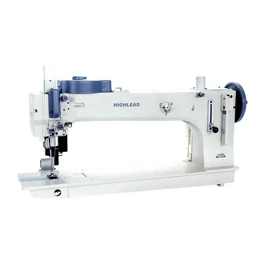
- Page 1 GG80018 Long Arm Extra Heavy Duty Zigzag Sewing Machine Instruction Manual Parts Catalog SHANGHAI BIAOZHUN HAILING SEWING MACHINERY CO., LTD.
-
Page 2: Table Of Contents
—INDEX— OPERATION INSTRUCTION PRECAUTIONS BEFORE STARTING OPERATION ……………………..…………………..………..SPECIFICATIONS .……………………………………………………………………………...….……… OILING…………………………………………………………………………………………….….……. THREADING ...…………………………………………………………………………………….…….… HEIGHT OF FEED DOG ……….……..………………………………………………………………..… NEEDLE………………………………………………………………………….………………….……… ZIGZAG TYPE…………………………………………………………………………………….…..…… REVERSE FEEDING AND STITCH COMPENSATION…………………………………………..…… WIDTH OF ZIGZAG AND LENGTH OF STITCH…………...………………….…...…………………... ACTION……………………………………………………….……………………………….……….…... SETTING CONTROL DEVICE……………………………………………………..………………….….. PARTS CATALOG A. ARM BED AND IT’S ACCESSORIES…………………………………………………………………… NEEDLE BAR AND TAKE-UP MECHANISM….……………………………………………...…………... -
Page 3: Precautions Before Starting Operation
1. PRECAUTIONS BEFORE STARTING OPERATION 1) Safety precautions: (1) When turning the power on, keep your hands and fingers away from the area around/under the needle and the area around the pulley. (2) Power must be turned off when the machine is not in use, or when the operator leaves the seat. (3) Power must be turned off when tilting the machine head, installing or removing the “V”... -
Page 4: Oiling
3. OILING Do not operate the machine, even if only for testing and or idling, unless it has been properly oiled at every spot and reservoir required lubrication. (Fig.1) Fig.1 4. THREADING Pass the thread through the path (Fig.2). The tension on the needle thread and the tension on the bobbin thread shuold be determined by the sewing materials. -
Page 5: Zigzag Type
7. ZIGZAG TYPE By changing cam(1),the zigzag type can be changed from one steps to two steps or three steps. Loosen the screw(2) , remove the cam(1) and replace the required one ( Fig.4) . Fig.4 Fig.5 8. REVERSE FEEDING AND STITCH COMPENSATION To feed the work toward you ,press down the switch for reverse feeding(1) .To compensate one or more stitch ,press down the switch for stitch compensation (2). -
Page 6: Action
10. ACTION The action of the reverse feeding , presser foot lifting and puller draging is regulated by the pneumatic valves(Fig.8). Fig.8 11. SETTING CONTROL DEVICE plugs Fig.9 Fig.10 First please locate the device (Fig.9), and arrange the pipes marked with A,B,C in sequence (Fig.10). After that connect the pipes(Fig.10) to the joint(maked with A,B,C) of the control device(Fig.9) in order .Finally insert the plugs(Fig.9) to motor. -
Page 7: Arm Bed And It's Accessories
A.ARM BED AND IT'S ACCESSORIES - 5 -... - Page 8 A.ARM BED AND IT’S ACCESSORIES Fig. Part No. Description Pcs. Remarks HM811B7101 Board Complete HM812B8001 Board H415080120 Screw H007013080 Retaining Ring H415080450 Screw HM813B8001 Block HM817B8001 HM031K8001 Spring HM815B8001 H401060100 Screw HM816B8001 Brand H415040120 Screw H005001040 Washer HM819B8001 Guard HM820B8001 Screw HM821B8001 Thread guide...
- Page 9 A.ARM BED AND IT’S ACCESSORIES Fig. Part No. Description Pcs. Remarks H415080450 Screw H005008080 Washer HM846B8001 Cover HM848B7101 The switch for stitch compensation H402040120 Cross recessed pan head screw - 7 -...
-
Page 10: Needle Bar And Take-Up Mechanism
B.NEEDLE BAR AND THREAD TAKE-UP MECHANISM - 8 -... - Page 11 B.NEEDLE BAR AND THREAD TAKE-UP MECHANISM Fig. Part No. Description Pcs. Remarks HM804C8001 Bushing H003002060 H005001060 Washer HM806C7101 Cam shaft complete H602050260 HM809C8001 Screw H7213C8001 Roller HM811C8001 Guide H415060180 Screw H415030120 Screw HM812C8001 Block HM813C8001 Slide block HM814C8001 Brand HM815C8001 Screw HM817C8001 Rob lever...
- Page 12 B.NEEDLE BAR AND THREAD TAKE-UP MECHANISM Fig. Part No. Description Pcs. Remarks HM839C8001 Block HM840C8001 Roller HM846C8001 H415060150 Screw H415060150 Screw HM842C8001 Block HM843C8001 Guide H7312G8001 Screw HM844C8001 Guide H401040060 Screw H415040080 Screw HM845C7101 Presser foot complete HM849C8001 Block HM852C8001 Platform H415060350 Screw...
-
Page 13: Upper Shaft Machanism
C.UPPER SHAFT MECHANISM - 11 -... - Page 14 C.UPPER SHAFT MECHANISM Fig. Part No. Description Pcs. Remarks HM805D8001 Crank H428060100 Screw H602050320 HM808D8001 Shaft H428060060 Screw HM809D8001 Link HM810D8001 Link HM811D8001 Shaft H424050040 Screw HM812D8001 HM813D8001 Screw HM816D8001 Joint H415050100 Screw HM818D8001 Thread take-up lever HM819D8001 Bushing HM821D8001 Upper shaft HM824D8001 Bushing...
-
Page 15: Cam Machanism
D.CAM MACHANISM - 13 -... - Page 16 D.CAM MACHANISM Fig. Part No. Description Pcs. Remarks HM804E8001 H415060250 Screw H003001060 H415060250 Screw H003001060 H415060250 Screw H003001060 HM808E8001 HM809E8001 HM810E8001 HM814E8001 Cover H415060160 Screw H431060060 Screw H415060160 Screw H431080100 Screw HM818E8001 Bearing HM819E8001 Washer GB/T1567 8×5×28 Bond HM821E8001 Gear (big) HM822E8001 Shaft HM823E8001...
- Page 17 D.CAM MACHANISM Fig. Part No. Description Pcs. Remarks HM846E8001 Spring HM847E8001 Shaft Ring H415040140 Screw H003002080 HM848E8001 Screw HM849E8001 Setting bracket - 15 -...
-
Page 18: Feed Mechanism
E.FEED MECHANISM - 16 -... - Page 19 E.FEED MECHANISM Fig. Part No. Description Pcs. Remarks HM805F8001 Left slide plate HM807F8001 Two steps Needle plate H7326E8001 Screw Right slide plate HM811F8001 H7326E8001 Screw H415060100 Screw HM812F8001 Cover HM818F8001 HM819F8001 Joint H007013035 Retaining ring HM820F8001 Crank H415050160 Screw HM821F7101 Reverse stitching arm complete HM824F8001 Slide block...
- Page 20 E.FEED MECHANISM Fig. Part No. Description Pcs. Remarks H003002060 HM854F7101 Link complete H415060180 Screw H003002060 H415060180 Screw HM856F8001 Feed connecting arm HM857F8001 Bushing HE033H8001 Collar HE034H8001 SM17/64"(6.75)×24 Screw HM860F8001 Bushing HM861F8001 Shaft H003001080 HM864F8001 Screw H415060120 Screw HM868F8001 Feed connecting arm H007013090 Retaining ring HM870F8001...
-
Page 21: Lower Shaft Machanism
F.LOWER SHAFT MACHANISM - 19 -... - Page 22 F.LOWER SHAFT MACHANISM Fig. Part No. Description Pcs. Remarks HM807G8001 H431060080 Screw HM808G8001 Link HM809G8001 Bearing HM810G8001 Baffle H415040060 Screw HM812G8001 Baffle H415040060 Screw H415080250 Screw H415050160 Screw H415050160 GB/T 70.1 M5×16 Screw H005010060 Washer H415050160 Screw HM814G8001 HM815G7101 Shaft complete Oil cup H415050160 Screw...
-
Page 23: Shuttle Hook Mechanism
G.SHUTTLE HOOK MECHANISM - 21 -... - Page 24 G.SHUTTLE HOOK MECHANISM Fig. Part No. Description Pcs. Remarks HM806H8001 HM807H8001 Block H431040040 Screw H415040100 Screw HM809H8001 Bushing H431050050 Screw HM810H8001 Bushing HM811H8001 Washer H401030060 Screw H005001030 Washer HM812H8001 Needle-protecting plate HM813H8001 Hook base H415040100 Screw HM814H8001 Cover H415080400 GB/T 70.1 M8×40 Screw HM841H8001 HM815H8001...
- Page 25 G.SHUTTLE HOOK MECHANISM Fig. Part No. Description Pcs. Remarks HM838H8001 Spring HM839H8001 Screw HM840H8001 Screw H431060060 Screw - 23 -...
-
Page 26: Thread Mechanism And Bobbin Winder Mechanism
H.THREAD MECHANISM AND BOBBIN WINDER MECHANISM - 24 -... - Page 27 H.THREAD MECHANISM AND BOBBIN WINDER MECHANISM Fig. Part No. Description Pcs. Remarks H6706N8001 Platform H6707N8001 H6708N8001 H7210J8001 Shaft H7213J8001 Crank H6713N8001 Bushing H6714N8001 H6715N8001 Spring H007013050 Retaining ring 5 H7205J8001 Shaft H6717N8001 Bobbin case H7214J8001 Wheel H6658B8001 Rubber ring H6720N8001 Spanner HA100H2150 SM9/64"(40)×11...
- Page 28 H.THREAD MECHANISM AND BOBBIN WINDER MECHANISM Fig. Part No. Description Pcs. Remarks HA310B0702 Tension release plate HA310B0701 Thumb nut HM824I8001 Thread guide H003008050 HM825I8001 Screw HM826I8001 Washer HA310B0705 Tension discs HM808I8001 Spring HM827I8001 Bushing HM828I8001 H415060160 Screw - 26 -...
-
Page 29: Accessories
I.ACCESSORIES - 27 -... - Page 30 I.ACCESSORIES Fig. Part No. Description Pcs. Remarks HM806K8001 Oil pan HM807K8001 Bracket(1) HM808K8001 Bracket(2) H801045200 Screw H409040050 Screw HM809K7101 Belt guard HM811K8001 Bracket(1) H415080120 Screw H415040060 Screw HM812K8001 Bracket(2) H409040050 Screw HM813K8001 Setting board HM814K8001 Screw HF913L8001 Setting bracket H7228D8001 Bobbin HA300J2220 Double head wrench...
- Page 31 SHANGHAI BIAOZHUN HAILING SEWING MACHINERY CO., LTD. ADD: NO.850 Shulin Road, Songjiang District Shanghai, P.R.China Zip Code: 201612 Overseas Business: TEL: 86-21-64853303 FAX: 86-21-64854304 E-mail:sales@highlead.com.cn http://www.highlead.com.cn The description covered in this manual is subject to change for improvement of the commodity without notice 2018.3. Printed...
Need help?
Do you have a question about the GG80018 and is the answer not in the manual?
Questions and answers