
Related Manuals for HIGHLEAD GA2688-1


Summary of Contents for HIGHLEAD GA2688-1
-
Page 1: Instruction Manual
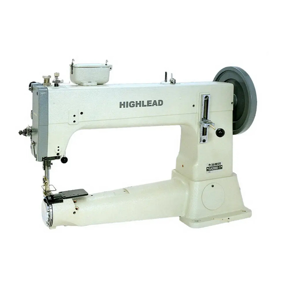
GA2688-1 Cylindrical Bed Extra-Heavy Duty Compound-Feed Lockstitch Sewing Machine Instruction Manual Parts Catalog SHANGHAI BIAOZHUN HAILING SEWING MACHINERY CO.,LTD. -
Page 2: Table Of Contents
≡CONTENT≡ 1. PRECAUTIONS BEFORES STARTING OPERATION ……………………………………………………………1 ■ Safety precautions………………………………………………………………………………………1 ■ Precautions before starting operation…………………………………………………………… 1 ■ Precautions for operating conditions …………………………………………………………… 1 2. SPECIFICATION ……………………………………………………………………………………………1 3. PREPARATION FOR OPERATION ……………………………………………………………………………2 ■ Cleaning the machine …………………………………………………………………………………2 ■ Examination………………………………………………………………………………………………2 ■ Lubrication………………………………………………………………………………………………2 ■... -
Page 3: Precautions Befores Starting Operation
1. PRECAUTIONS BEFORES STARING OPERATION 1) Safety precautions: (1) When turning the power on, keep your hands and fingers away from the area around/under the needle and the area around the pulley. (2) Power must be turned off when the machine is not in use, or when the operator leaves the seat. (3) Power must be turned off when tilting the machine head, installing or removing the “V”... -
Page 4: Preparation For Operation
3、PREPARATION FOR OPERATION (1) Cleaning the machine Before leaving the factory, the machine parts are coated with rust-preventive grease, which may be hardened and contaminated by dust during storage and shipment. This grease must be removed with gasoline. (2) Examination Though every machine is confirmed by strict inspection and test before leaving the factory, the machine parts may be loose or deformed after long distance transportation with jolt. -
Page 5: Winding Of Bobbin Thread
Fig.2 5、WINDING OF BOBBIN THREAD (Fig.3) (1) Push the bobbin ③ on the bobbin winder shaft as far as it will go. (2) Bring the thread forward toward the bobbin and wind from below in clockwise direction several times around the bobbin. (3) Push the lever ⑤... -
Page 6: Threading
7、THREADING (Fig.4) Raise the needle bar to its highest position and route the upper thread in the order illustrated below. Fig.4 8、REMOVING AND INSERTING THE BOBBIN (1) Removing: Open the shuttle race cap and the bobbin holder, then take out the bobbin. Installation: Put the bobbin in the rotary hook case, Permit about 5 cm of bobbin thread to hand down freely. -
Page 7: Tension Of The Upper Thread
Fig.5 (1) Tension of the Upper thread Before adjusting the tension of the upper thread, be sure that presser foot is let down. To adjust tension, turn serrated nut on tension device to the right (clockwise) to increase tension and to the left (counter-clockwise) if you desire to decrease the tension. -
Page 8: Adjustment Of Walking Foot And Presser Foot
11、ADJUSTMENT OF WALKING FOOT AND PRESSER FOOT (Fig.7) (1) The alternating movement on the walking foot and presser foot can be adjusted by changing the position relations of the parts of the presser foot lifting mechanism. (2) Changing the position relation of the connecting link 2 and the crank 3 can complete the adjustment. -
Page 9: Adjusting The Height Of The Needle Bar
14、ADJUSTING THE HEIGHT OF THE NEEDLE BAR (Fig.10) When the needle bar is at its highest point, normally the measurement between the highest point of the needle plate and the needlepoint is 28 mm. When this distance need to be adjusted, the steps is as follows: (1) Take down the face plate, adjust the needle bar to its highest position. - Page 10 A.ARM BED AND ITS ACCESSORIES — 8 —...
- Page 11 A.ARM BED AND ITS ACCESSORIES Fig. Part No. Description Pcs. Remarks H7208B8001 Arm H7210B8001 Bed H7215B8001 Oil pipe H7216B8001 Oil wick HA307B0674 Rubber plug H7217B8001 Needle bar guide bracket stud bushing HA100C2020 Screw SM15/64(28)×10 HA100C2020 Screw SM15/64(28)×10 H7218B8001 Presser bar bushing HA305E0662 Screw SM15/64(28)×4.5 H7219B8001 Pin...
- Page 12 A.ARM BED AND ITS ACCESSORIES Fig. Part No. Description Pcs. Remarks H7255B8001 Thread take-up spring guide plate H3410C301K Screw SM9/64(40)×6.5 H7257B8001 Screw SM1/8(44) H7258B8001 Nut SM1/8(44) H7259B8001 Tension spring H7260B8001 Tension disc H7261B8001 Thread tension regulator complete base HA7311CC06 Screw SM9/64(40)×6 H7262B8001 Thread guide H3410C301K Screw...
- Page 13 B.NEEDLE BAR AND THREAD TAKE-UP MECHANISM — 11 —...
- Page 14 B.NEEDLE BAR AND THREAD TAKE-UP MECHANISM Fig. Part No. Description Pcs. Remarks H7204C8001 Pulley H7205C8001 Screw SM5/16(24)×22.4 H7206C8001 Screw SM5/16(24)×21.4 H7208C8001 Arm shaft HA108G0661 Collar HA105D0662 Screw SM1/4(40)×6 H7209C8001 Thread thke-up cam H7210C8001 Needle bar connecting base link screw H403060120 Screw GB/T68 M6×12 H4933K8001 Screw SM1/4(40)×10...
- Page 15 C.LOWER SHAFT MECHANISM — 13 —...
- Page 16 C.LOWER SHAFT MECHANISM Fig. Part No. Description Pcs. Remarks H7204D8001 Eccentric H7205D8001 Screw SM15/64(28)×12 H7206D8001 H415060250 Screw GB/T70.1 M6×25 H4728H8001 Washer H7237D8001 Bearing K43×48×17(NTN) H7207D8001 Eccentric cover H2000B2050 Screw SM11/64(40)×9 H7208D8001 Crank connecting rod H7209D8001 Crank connecting rod pin H7210D8001 H7211D8001 Screw SM3/16(32)×18...
- Page 17 C.LOWER SHAFT MECHANISM Fig. Part No. Description Pcs. Remarks H2405D0664 Screw SM15/64(28)×14 H7229B8001 Bushing H2405D0664 Screw SM15/64(28)×14 H7240D7101 Shuttle hook KSP-204N(佐文) — 15 —...
- Page 18 D.FEEDING MECHANISM — 16 —...
- Page 19 D.FEEDING MECHANISM Fig. Part No. Description Pcs. Remarks H7205E8001 Feed cam H7206E8001 Screw SM15/64(28)×6 H7207E8001 Feed cam cover H2000B2050 Screw SM11/64(40)×9 H7208E8001 Feed forked connection H7209E8001 Feed forked connection crank pin H2010J0066 Nut SM9/32(28) H7210E8001 Stitch length connecting link H7211E8001 Stitch length connecting link crank pin H415050140 Screw GB/T70.1 M5×14 H7212E8001 Stitch length adjusting pin...
- Page 20 D.FEEDING MECHANISM Fig. Part No. Description Pcs. Remarks H7231E8001 Screw SM3/16(28)×9.5 H7232E8001 Stitch length outside plate HA104F0654 Screw SM15/64(28)×9 H7232B8001 Bushing HA100C2020 Screw SM15/64(28)×10 H7231B8001 Bushing HA3411D308 Screw SM15/64(28)×7 H7233B8001 Bushing H2405D0664 Screw SM15/64(28)×14 — 18 —...
- Page 21 E.PRESSER FOOT MECHANISM — 19 —...
- Page 22 E.PRESSER FOOT MECHANISM Fig. Part No. Description Pcs. Remarks H7204F8001 Presser foot H7205F8001 Screw SM9/64(40)×14 HA710P0673 SM9/64(40) H7206F8001 Finger guard H7207F8001 Presser bar H7208F8001 Presser bar spring H7209F8001 Thumb screw SM5/8(28) H7210F8001 H7211F8001 Walking foot HA719B0709 Screw SM11/64(40)×7 H7212F8001 Presser bar H7213F8001 Screw H7214F8001...
- Page 23 F.UPPER FEED LIFTING ROCK SHAFT MECHANISM — 21 —...
- Page 24 F.UPPER FEED LIFTING ROCK SHAFT MECHANISM Fig. Part No. Description Pcs. Remarks H7204G8001 Presser foot lifting eccentric HA307C0066 Screw SM1/4(40)×6 H7205G8001 Eccentric connecting link H7206G8001 Screw H7207G8001 Washer H7208G8001 SM11/32(28) H7209G8001 Adjusting crank H7210G8001 Screw SM5/16(18) H7211G8001 Presser foot lifting shaft H7212G8001 Presser foot lifting shaft crank H415060140...
- Page 25 G.NEEDLE BAR ROCKING MOTION MECHANISM — 23 —...
- Page 26 G.NEEDLE BAR ROCKING MOTION MECHANISM Fig. Part No. Description Pcs. Remarks H7204H8001 Needle bar rocking connecting link H7219E8001 Screw H007013080 Retaining ring-E type GB/T896 8 H7206H8001 Adjusting crank H7207H8001 Adjusting crank base H7208H8001 Screw H7210G8001 Screw H7209H8001 Needle bar rock shaft H7210H8001 Collar HA105D0662...
- Page 27 H.KNEE LIFTER MECHANISM —25 —...
- Page 28 H.KNEE LIFTER MECHANISM Fig. Part No. Description Pcs. Remarks H7204I8001 Knee lifter lever H7205I8001 Screw SM15/64(28)×6 H7206I8001 Knee lifter lever base HA300J2280 Screw SM15/64(28)×6.5 H7207I8001 Screw SM15/64(28)×8 H7208I8001 Knee lifter rod H7205I8001 Screw SM15/64(28)×6 H7209I8001 Coil spring H7210I8001 Screw H7211I8001 Screw SM15/64(28)×13 H7212I8001...
- Page 29 I.BOBBIN WINDER MECHANISM — 27 —...
- Page 30 I.BOBBIN WINDER MECHANISM Fig. Part No. Description Pcs. Remarks H6706N8001 Bobbin winder plate H6707N8001 H6708N8001 H7210J8001 Bobbin winder crank shaft H7213J8001 Bobbin winder crank H6713N8001 Bushing H6714N8001 H6715N8001 Bobbin winder spring H007013050 Retaining ring-E type GB/T896 5 H7205J8001 Bobbin winder shaft H6717N8001 Bobbin base H7214J8001...
- Page 31 J. ACCESSORIES — 29 —...
- Page 32 J.ACCESSORIES Fig. Part No. Description Pcs. Remarks H7207K8001 Silicon oil box H7208K8001 Cover H605030400 GB/T119.2 3×40 H34411C410 Screw SM9/64(40)×4 H7209K8001 Spring H3215K0693 Screw SM9/64(40)×5 H7210K8001 Thread guide H7211K8001 SM3/32(56) HA800F2020 Screw SM15/64(28)×13.5 HB00001050 Hexagon socket screw key GB/T5356 5 HG00001040 Hexagon socket screw key GB/T5356 4 HB00001030...
- Page 33 K. Belt cover Large component — 31 —...
- Page 34 K.Belt cover Large component Fig. Part No. Description Pcs. Remarks H7226K8001 Belt cover H7227K8001 Upper cover H2000O0360 Screw SM11/64(40)×7 H7236K8001 Belt brace HA300J2280 Screw H005009060 Washer GB/T 859 6 H801045200 Screw GB/T 99 4.5×20 HA300J2230 Washer — 32 —...
- Page 35 SHANGHAI BIAOZHUN HAILING SEWING MACHINERY CO.,LTD. ADD: No.850 Shulin Road, Songjiang District,Shanghai, P.R.China Zip Code: 201612 Overseas Business: TEL: 86-21-64853303 FAX: 86-21-64854304 E-mail:sales@highlead.com.cn http://www.highlead.com.cn The description covered in this manual is subject to change for improvement of the commodity without notice 2016.12. Printed...
Need help?
Do you have a question about the GA2688-1 and is the answer not in the manual?
Questions and answers