Table of Contents
Advertisement
Quick Links
Advertisement
Table of Contents

Related Manuals for Dynamica HALO RB-10


Summary of Contents for Dynamica HALO RB-10
- Page 1 HALO RB-10 UV-VIS SPECTROPHOTOMETER HALO RB-10 Spectrophotometer Instruction Manual Please read through this manual carefully and store it in a safe place. Before using the instrument, please read the safety instructions and precautions carefully Keep this manual in a safe place nearby to access...
- Page 2 INSTRUCTION MANUAL Model HALO RB-10 UV-Vis Spectrophotometer Read and keep this manual Read the safety instructions carefully and · understand them before using equipment. Keep this manual at hand for reference. · Dynamica Ltd. Version No: V1.1...
-
Page 3: Table Of Contents
1.2.2 Installation Environment ..........1- 2 Check of Contents............1- 3 Check of Voltage and Fuse ..........1- 4 Side Panel of the HALO RB-10 ........1- 5 Connection of Power Cord and Grounding Wire ....1- 5 Connection of Printer............1- 6 Local Remote Switch............1- 7 LCD Brightness adjustment port ........1- 7... - Page 4 FUNCTION........................2- 1 Application..............2- 1 Operating Principle............2- 2 2.2.1 Optical System ...............2- 2 2.2.2 Signal Processing and Control System ......2- 3 Proper Use of Spectrophotometer........2- 3 2.3.1 Selection of Solvent............2- 3 2.3.2 Special Samples.............2- 4 Functions................2- 4 2.4.1 Quantitative Analysis............2- 4 2.4.2 Wavelength Scan ............2- 5 2.4.3 Secondary Processing Functions........2- 5 2.4.4 Secondary Processing Functions........2- 5...
- Page 5 3.6.2 Step by Step Operation ..........3- 33 MAINTENANCE......................4- 1 Self-diagnosis and Automatic Adjustment......4- 1 Confirmation of Specifications........4- 1 4.2.1 Wavelength Accuracy.............4- 1 4.2.2 Spectrum BandWidth .............4- 1 4.2.3 Check for Baseline Flatness...........4- 1 Periodical Inspection ............4- 1 4.3.1 Cleaning of Sample Compartment .........4- 2 4.3.2 Cleaning of Sample Compartment Window ....4- 3 Troubleshooting Table............4- 5 REPLACEMENT PARTS....................5- 1...
-
Page 6: Preface
The Model HALO RB-10 Spectrophotometer is intended for the purpose of photometric analysis. Do not use it for any other purpose. The Model HALO RB-10 is designed for use by persons having a basic knowledge of chemical analysis. Other persons should operate the instrument in the presence of someone who has such basic knowledge. -
Page 7: Important
IMPORTANT Precautions on Electromagnetic Wave Interference 1. Possible Electromagnetic Wave Interference Caused by This Instrument When this instrument is used in a residential area or an adjacent area thereto, it may cause interference to radio and television reception. To prevent this, use the specified system connection cables in strict accordance with the instruction manual. -
Page 8: Warranty On Product
• Confirm that any other device connected with the instrument is not affected by electromagnetic wave interference. Warranty on Product The Model HALO RB-10 Spectrophotometer is warranted to operate according to the specifications given in the instruction manual, provided it is used in accordance with the instructions described in the manual. - Page 9 Limitations and Exclusions on Warranty Note that this warranty is void in the following cases, even if they occur within the warranty period. (a) Failure due to operation at a place not meeting the installation requirements specified by us (b) Failure due to power supply voltage/frequency other than specified by us or due to abnormality in power supply (c) Corrosion or deterioration of the tubing due to impurities contained in reagent, gas, air or cooling water supplied by...
-
Page 10: Technical Service
Technical Service Installation of this instrument shall be carried out by or under supervision of qualified service personnel of Dynamica Corporation or its authorized service agent. Before installation of the instrument, the user shall make preparations for satisfying the installation requirements in accordance with the instruction manual. -
Page 11: Disposal This Instrument
Disposal this instrument When you discard equipment, please check and discard a related statute etc. or ask the service section of Dynamica. Other Precautions 1. Handling of Chemicals and Samples The user is responsible for following relevant legal standards and regulations in handling, storage and discarding of chemicals and samples used in analytical operations of this instrument. -
Page 12: Safety Summary
SAFETY SUMMARY PRECAUTIONS ON SAFETY Before using the Model HALO RB-10 Spectrophotometer, be sure to read the following safety instructions carefully. GENERAL SAFETY GUIDELINES • Follow all the operating procedures provided in this manual. • Installation and maintenance of the product shall be carried out by service personnel qualified therefor. - Page 13 SAFETY SUMMARY General Safety Guidelines (Cont’d) “NOTICE” and “NOTE” are heading words which do not concern personal safety directly. NOTICE : Used to indicate an instruction for preventing damage to the product. Used to indicate an instruction for ensuring correct use of NOTE: the product and accurate analysis therewith.
- Page 14 SAFETY SUMMARY General Safety Guidelines (Cont’d) This instruction manual contains the following cautious instructions. The warning “DANGER” does not apply to this product. DANGER • Electric Shock in Contact with Dangerous High Voltage WARNING (500 V) In contact with D lamp power supply voltage (500 V), you may receive an electric shock to cause fatal or serious injury.
- Page 15 SAFETY SUMMARY General Safety Guidelines (Cont’d) • Burn in Contact with High Temperature CAUTION The D lamp and WI lamp reach a high temperature. They can burn you if touched. Before replacing or adjusting the lamp, turn off the POWER switch and wait until it cools down sufficiently.
-
Page 16: Remarks On Safety Of Spectrophotometer
SAFETY SUMMARY Remarks on safety of spectrophotometer Electricity Confirm the power supply to the spectrophotometer. Fluctuation in voltage or noise on the power line would not only affect the spectrophotometer main unit adversely but also cause an accident. Be sure to provide grounding connection along with power connection. - Page 17 SAFETY SUMMARY Computer Virus If programs or data has suddenly been destroyed, if an unexpected operation takes place or if an abnormal display appears on the screen, your personal computer may have been infiltrated by a computer virus. The computer virus is a rogue program that secretly invades a personal computer and operates it willfully while destroying memorized data.
- Page 18 SAFETY SUMMARY Personal Computer (PC) Do not turn off the PC power supply alone. If the PC power supply is turned off during access to the hard disk or floppy disk, the PC may malfunction and the data or software stored in it may be destroyed. To turn off the PC power supply, be sure to complete the spectrophotometer control and data processing program (PC software) before taking the shutdown procedure for the system...
-
Page 19: Warning Label
SAFETY SUMMARY Warning Labels The warning labels shown below are attached to the Model HALO RB-10 Spectrophotometer. SAFETY-8... -
Page 20: Unpacking
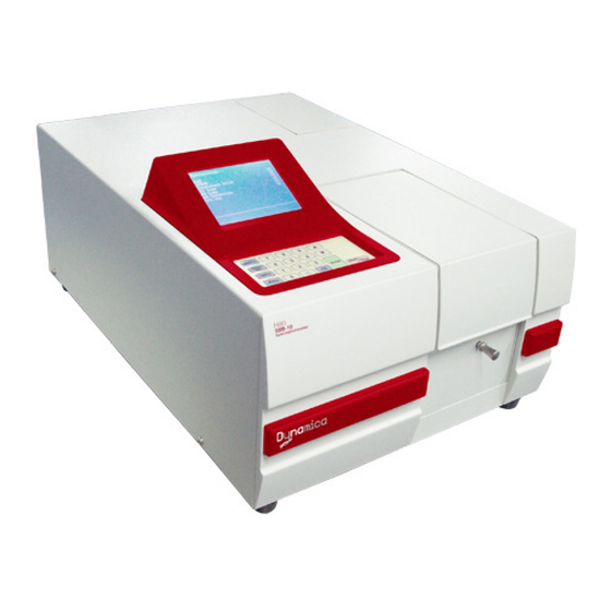
Since the spectrophotometer weighs about 20 kg, care should be taken when removing it. Fig. 1-1 Model HALO RB-10 Spectrophotometer Note: The light source-switching mirror is secured with the sponge rubber material for transport at shipment from the factory. After using, open the light source cover and remove the protective sponge from the light source-switching mirror. -
Page 21: Installation Environment
Grounding line resistance of 100Ω or less is required. Note: If warning labels cannot be read because of stains or because they are coming off, please notify the local Dynamica sales representative or service office. New labels will be provided. -
Page 22: Check Of Contents
The above cautions should be strictly observed. 1.3 Check of Contents After unpacking, check the contents of delivery against the packing list. In the HALO RB-10, you should find the following items. a. HALO RB-10 Main unit b. Operating Manual c. -
Page 23: Check Of Voltage And Fuse
Check them for the correct quantity against the packing list supplied with the instrument. Fig. 1-3 Rectangular Standard Four Cell Holder for HALO RB-10 Accessory 1.4 Check of Voltage and Fuse Warning: Before checking, make sure the power cord is not connected. -
Page 24: Side Panel Of The Halo Rb-10
220 V 3.15A Fig. 1-3 the Power Connector of Model HALO RB-10 1.5 Side Panel of the HALO RB-10 The HALO RB-10 has 6 ports on the side panel. They are a. Power connector and switch b. Printer port c. LCD brightness adjustment port d. -
Page 25: Connection Of Printer
(2) When using a power extension lead, make sure the ground wire is securely connected to the grounding terminal. Fig. 1-3 How to Ground the Model HALO RB-10 1.7 Connection of Printer A printer can be connected to the instrument using a standard parallel printer cable. -
Page 26: Local Remote Switch
Please refer to the relevant printer instruction manual to install the printer. 1.8 Local-Remote switch The HALO RB-10 can be controlled by the optional PC software, or simply via keypad control. Please put the Local-Remote switch to Local when using the keypad and LCD on the HALO RB-10. -
Page 27: Function
Chapter 2 Function 2.1 Theory The Model HALO RB-10 Spectrophotometer is designed for absorption analysis of liquid, solid and gaseous samples in the ultraviolet and visible spectral regions. Measurements are based on the Lambert-Beer law, as shown in Figure 2-1 A monochromatic beam with intensity ‘I... -
Page 28: Optical System
-ε.c.l = 10 = τ Fig. 2-1 Lambert -Beer law 2.2 Principle of Operation 2.2.1 Optical System Figure 2-2 shows the optical system of the Model HALO RB-10. Fig 2-2 Optical System of Model HALO RB-10 Spectrophotometer... -
Page 29: Signal Processing And Control System
The HALO RB-10 is a ratio beam system, which features a half mirror to split the beam into a reference beam and sample beam. This design makes it possible to attain a highly stable photometric value, surpassing the analytical performance of a typical single beam spectrophotometer. -
Page 30: Special Samples
Where, ‘r’ varies according to the reflectance of the substance. 2.4 Functions 2.4.1 Quantitative Analysis The Model HALO RB-10 is capable of calculating the concentration of a sample after generating a standard calibration curve or by entering a factor into the system. -
Page 31: Wavelength Scan
(3) Data can be calculated for rate assay. 2.4.4 Secondary Processing Functions The Model HALO RB-10 can store the measured spectrum and its change with time in the memory. A variety of secondary processing functions can be applied to the stored data. -
Page 32: Automatic Calibration And Self Diagnosis Functions
(c) Expansion of Y Axis Numeric values can be input to specify a desired expansion range for the ordinate. (3) Smoothing A spectrum with a large noise level can be corrected to form a smooth curve. (4) Differentiation The data of a spectrum currently displayed on the LCD are differentiated. First order derivatives may be obtained. -
Page 33: Specification
2.5 Specification Table 2-1 HALO RB-10 Specifications Item Description Monochromator Equipped with high resolution concave diffraction grating and Seya-Namioka mount Wavelength range 190~1100nm Spectral bandpass Stray light ≤0.05%T (220nm NaI, 340nm NaNO Wavelength Accuracy ±0.5nm Wavelength Repeatability 0.5nm Photometric mode... -
Page 34: Operation Method
Numeric keys Special function keys Control Keys The function of each key on the Model HALO RB-10 Key Panel is as follows Main Menu Lists the five data processing functions and returns to the initial main menu frame when pressed. -
Page 35: Starting Up The Spectrophotometer
Start/Stop Start or stop the measurement. 3.2 Starting up the Spectrophotometer 3.2.1 Initialization At power up, the HALO RB-10 spectrophotometer automatically runs a self-diagnostic sequence that checks the following system in the INITIALIZATION frame. EPROM... -
Page 36: Main Menu
WI lamp AD conversion 656.1nm Upon completion of each test item, the message <OK> will display if the item’s function is normal or the message <NG> will display if the item’s function is abnormal. CONSULT THE TROUBLESHOOTING SECTION IF AN ERROR MESSAGE OCCURS DURING INITIALIZATION. -
Page 37: Selecting Options From The Main Menu
Current Wavelength and 500.0 0.001 Absorbance/Transmittance Main Menu Photometry W avelength Scan Menu and Options Time Scan available System Data Display Select Function Sel: _ Action bar/user prompt The wavelength and photometric value indicated at the top of the Main Menu remain displayed on the submenu. -
Page 38: Photometry
A submenu list appears on the screen as shown in the illustration below: 500.0 0.001 %T/ABS NUM WL WL Setting Data Mode End Setting Select Function Sel: _ 1. Step by Step Operation This section provides step-by-step instructions for how to use your Model HALO RB-10 spectrophotometer in the Photometry mode. - Page 39 To select the function displayed on the menu, you can use: a) The numeric key as the function key, just press the number, such as 1 to start the Photometry sub menu. The HALO RB-10 will automatically enter the submenu after pressing the numeric key.
- Page 40 500.0 0.001 %T/ABS NUM WL WL Setting Data Mode End Setting Select Function Select either ABS (Absorbance) or %T (Transmittance) by pressing the corresponding numeric key. The photometry value displayed on the top right hand side of the screen will change accordingly. Press 2 on the keyboard to obtain the following screen.
- Page 41 500.0 0.001 WL1(nm) 900.0 WL2(nm) 800.0 WL3(nm) 700.0 Select Function Sel: _ The number of wavelengths displayed is specified under WL NUM. Press the numeric key to modify the wavelength; the wavelength being changed will be highlighted. Enter the required wavelength by pressing the numeric key; press Enter to confirm setting.
- Page 42 Photometry test. 4. Running a Photometry Test After Autozero, the HALO RB-10 is ready for Photometry Test; data obtained will be based on the Autozero data. Press Start/Stop on the keyboard to begin a photometry test.
-
Page 43: Ratio Mode
Display the current 500.0 Current data wavelength position %T/ABS 900.0nm 95.3 Result of the 800.0nm 98.6 measurement 700.0nm 900.0nm 65.3 Second set of data Wavelength Defined 800.0nm 28.6 in setup submenu 700.0nm 45.0 Press START Measure 1 Print Press 1 on the keyboard to print the analysis results. When the numbers of the data exceed the display area of the LCD, press the ▲... - Page 44 Step by Step Operation 1. RATIO parameter Setup To select the function displayed on the menu, a. Press the number to setup the parameters. For example, press 2 to define the Wavelength used in the ratio. b. To return to the previous menu, press Clear Return c.
- Page 45 The HALO RB-10 automatically autozeroes on the selected wavelength before a RATIO Test. 4. Running a RATIO Test HALO RB-10 is now ready for RATIO Test; the test will be based on the data collected in the Autozero cycle. Press Start/Stop on the keyboard to begin test.
- Page 46 500.0 0.001 Diff Ratio 0.001 -0.001 -0.002 0.002 1.500 0.001 -0.001 -0.002 0.002 1.500 0.001 -0.001 -0.002 0.002 1.500 Press START Measure Print The definition of the <DIFF> and <Ratio> is: If the <WL> number is 2, the <DIFF> value and <RATIO> value are calculated from the following formula.
-
Page 47: Using The Concentration Mode
To select the function displayed on the menu, the operator can use a. The numeric key as the function key, just press the number, such as 2 to start the Photometry submenu. The HALO RB-10 will automatically enter the submenu after the numeric key is pressed. - Page 48 -K factor concentration Select Function: _ analysis k-factor To select 1st, press 5 to define the number of standard sample for the calibration curve. The number of standard sample that can be used in the HALO RB-10 is 1~20. 3-15...
- Page 49 Press 6 for <STD Data> to input the concentration of the standard sample. 500.0 0.001 Concentration Input STD 10.0 20.0 30.0 Select Function Sel:_ Beginning Autozero After setting the parameter, press 0 and the system will display the following menu. 500.0 0.001 Concentration...
- Page 50 500.0 0.001 STD TEST Place Standard and Press START Place your first standard sample in the cell holder, close the sample compartment and then press Start/Stop . Replace with the next standard sample and then press Start/Stop again. After all standards are measured, a sub menu will appear on the screen as shown below.
- Page 51 500.0 0.002 1.000 -1.000 30.0 Process Measure Print Press 1 to choose the <Process> function to define how the data is processed, you can also enter the sample concentration measurement mode in this menu. Press 2 to enter the sample concentration measurement mode directly Post-run Processing Press 1 on the keyboard to display the <...
- Page 52 <Measure>: Measure the concentration of sample. <Data>: List all data of standards. <R>: Correlation coefficient Selecting Concentration Type: K – factor Press 2 in the concentration type menu and the following submenu will appear 500.0 0.001 Concentration NUM WL WL Setting Zoom Concentration Type k-factor...
- Page 53 Post-run Processing Press 1 on the keyboard to display the processing interface. 500.0 0.001 Process Zoom Graph Measure Data Select Function Sel:_ The definition of the post-run processing option is outlined below: <Zoom>: Re-scale either or both axes <Graph>: Display the standard calibration curve <Measure>: Measure the concentration of sample.
-
Page 54: Wavelength Scan Mode
To select the function displayed on the menu, the operator can use a. The numeric key as the function key, just press the number, such as 1 to set the wavelength for a scan. The HALO RB-10 will automatically enter the submenu after pressing the numeric key. -
Page 55: Definition Of The Options
Enter the <START WL> or <STOP WL> wavelength by pressing the numeric key on the keyboard and then press Enter Press 0 on the keyboard to save the setup. The HALO RB-10 will check the setup automatically. If the scan range is under 10nm, the HALO RB-10 will not start until a correct range has been entered. -
Page 56: Baseline Correction
%T: 0.0%~1000.0% ABS: -3.00~3.00 E(S): 0-600.0 Set up the <Upper Limit>, <Lower Limit>, <Scan speed> as in the procedure shown above NOTE: To enter a negative value, press the key -/. before entering the numeric key, the key will act as <-> (minus). Otherwise the key acts as “.”... -
Page 57: Beginning A Wavelength Scan
500.0 0.002 Wavelength Scan Baseline Correction Press START Measure Press Start/Stop to begin a baseline scan using the setup saved. NOTE: a) While scanning is in progress, the compound key Start/Stop is used as [STOP], otherwise it acts as [START]. b) If the parameters are not changed, the system will prompt you to correction baseline again. -
Page 58: Post-Run Processing
Press Start/Stop on the keyboard to begin a sample scan after the baseline correction is completed. Press Start/Stop key again to interrupt the scan in progress. 500.0 -0.001 1100 Select Function:_ Process Baseline Print Note: The prompt Baseline again will appear on the screen. If the scan parameters are identical, it is not necessary to perform Baseline correction again. - Page 59 Post-run processing function is outlined below: 1) <Zoom> RE-scale either or both axes 2) <Peak> Lists the value of the peaks of a spectrum. 3) <Valley> Lists the value of the valleys of a spectrum 4) <All Data> Lists all data of wavelength scan. 5) <Smooth>...
- Page 60 NOTE: The parameter of rescale cannot exceed the parameter set in the Wavelength Scan interface. Listing the Peaks and Valleys of a Spectrum Press 2 on the keyboard to select <PEAKS>; the Abs or the %T value of the peak will be listed: 500.0 0.001 Peak...
-
Page 61: Wavelength Scan Sampling Internal List
Printing a Spectrum or Data List Press 1 to print the spectrum or the data list. The HALO RB-10 can be configured for automatic printing of the Spectrum after the tests are completed. Refer to the Printer configuration menu for detail. -
Page 62: Time Scan
To select the function displayed on the menu, the operator can use a. The numeric key as the function key, just press the number, such as 5 to define the Scan Time sub menu. The HALO RB-10 will automatically enter the submenu after the numeric key is pressed. -
Page 63: Beginning A Time Scan
Data Mode Press 2 on the keyboard, the data mode selection will be highlighted. The Action Bar/user prompt display the section of the data mode. - <1- %T - % Transmittance> - <2- ABS – Absorbance> Upper Limit and Lower Limit The <Upper Limit>... -
Page 64: Post Run Processing
500.0 -0.001 3.000 -1.000 Select Function:_ Process Print 3.5.4 Post-Run Processing Press 1 on the keyboard, and the Post-Processing commands 1-7 are listed The definition of the functions is outlined 1) <Zoom> Expands either or both axes 2) < Peak> Lists the peaks of a spectrum 3) <Valley>... -
Page 65: Time Scan Sampling Internal List
Y-axis value. Press 0 to end setting the parameters and soon you will get the new spectrum rescaled. NOTE: 1. The parameter of rescale cannot exceed the parameter set in the Time Scan interface. 3.5.5 Time scan sampling internal List Time scan sampling internal list as follows. -
Page 66: System Setting
3.6 System Setting 3.6.1 Using System Mode Press 4 on the keyboard. A submenu list appears on the screen as shown in the illustration below. 500.0 -0.001 System Wavelength Calibration Lamp Print Set GLP/GMP 0.0%T Select Function:_ Sel:_ 3.6.2 Step by Step Operation Using the System Menu Press the numeric key on keyboard and the submenu will be displayed on the screen. - Page 67 500.0 -0.001 Wavelength Calibration Please Wait The entire calibration procedure is automatic and uses the 656.1nm emission line from the deuterium lamp. Note: If there is any error, the system will return to the system menu. If there is no error, the system will return to the main menu. <LAMP>...
- Page 68 End Setting Select Function:_ Items 3 and 4 are a timer for the D2 and WI lamps respectively. The HALO RB-10 maintains a timer on the hours of use of the D2 or the WI lamp for service purpose. The memory is non-volatile; the memory will not be erased by power off.
- Page 69 Print Set up Press 1 on the keyboard to select the required printer. The HALO RB-10 supports printers that uses the following printing protocols; ESC/P; DPU or PCL/3. A typical supplier for ESC/P is EPSON, for DPU is SEIKO, for PCL/3 is HP. Consult your distributor to obtain the latest list of compatible printers.
- Page 70 NOTE: After you press 0 on the keyboard, the setting will be saved in non-volatile memory of the HALO RB-10. GLP/GMP Wizard The GLP/GMP Wizard is a self-diagnosis function that assists the user to perform day to day system calibration and instrumentation qualification as required by Good Laboratory Practice.
- Page 71 500.0 -0.001 GLP/GMP WL Accuracy 0.0 OK WL Reproducibility Bandpass Noise Level Baseline Stability Baseline Flatness Hardware Print Summary Report Select Function Sel:_ The following function can be performed automatically 1) WL Accuracy 2) WL Repeatability 3) Bandpass 4) Noise Level 5) Baseline Stability 6) Baseline Flatness 7) Hardware...
- Page 72 2. <WL Reproducibility> The HALO RB-10 will perform a wavelength scan from 660.0 to 650.0nm as in the first stage of the WL Accuracy test. The maximum value of wavelength will be located, then the motor moves from 650.0 to 190.0nm, and then from 190.0 to 660.0nm.
- Page 73 4. <Noise Level> After a time scan of 300S at 500.0 nm, the HALO RB-10 will identify the maximum value and the minimum value of the measured data. The noise level value is the difference between the maximum value and the minimum value (peak to peak). If the noise level value less than 0.001ABS, the item will display <OK>.
- Page 74 Press 7 on the keypad, the display will change to as below: 500.0 -0.001 HARDWARE EPROM Wavelength Drive D2 Lamp WI Lamp AD Conversion Select Function Sel:_ After 5 Seconds, the system will return to the GLP/GMP Menu. Press 1 to print out the data.
- Page 75 Press 1 or 2 to change the data mode. Press [Goto WL] to enter the new <WL value >and the motor will move to the new position. 3-42...
-
Page 76: Maintenance
Chapter 4 Maintenance 4.1 Self Diagnosis and Automatic Adjustment The Model HALO RB-10 spectrophotometer is capable of executing self-diagnosis and automatic adjustment immediately after the power switch is turned on. For details, refer to chapter 3. 4.2 Confirmation of Specifications 4.2.1 Wavelength Accuracy... -
Page 77: Cleaning Of Sample Compartment
4.3.1 Cleaning of Sample Compartment The sample compartment is susceptible to contamination the compartment should be cleaned if a sample is spilled inside. Remove the respective parts from the compartment as shown in Fig. 4-1 through Fig. 4-3. If they are cleaned, be sure to dry them thoroughly before reassembling them. - Page 78 Fastening pin Fastening screw Holder Base Fig. 4-2 Remove the Fastening screw Removal direction Fig. 4-3 Remove the Cell Holder Take out the sample compartment base and clean the sample compartment. After cleaning the sample compartment, reinstall the sample compartment. 4.3.2 Cleaning the Sample Compartment Windows If the transparent window of the sample compartment is contaminated, remove the window plate, and then clean it completely.
- Page 79 Be sure to wash your hands thoroughly before cleaning the window, and then wipe off the contaminant with a soft paper or cloth soaked with alcohol and ether solution (mixed in a ratio of 1 to 1). CAUTION: Pinch both ends of the window plate with your fingers to set it back in the sample compartment.
- Page 80 Wavelength calibration values a. Execute CALIBRATION. appears at the bottom of the have been deleted. b. Contact the nearest Dynamica agent if screen during initialization. the error display does not go off even after executing CALIBRATION. LAMP or WI LAMP Error is Lamp filament has failed Replace the lamp.
-
Page 81: Replacement Parts
Chapter 5 Replacement Parts 5.1 Consumables and Spare Parts The following parts are consumables. Contact the nearest Dynamica agent before consuming all of them. WI Lamp (Tungsten Iodide Lamp): P/N: 25-03-0001 Lamp (Deuterium Lamp): P/N: 25-02-0013 Main Power Fuse: P/N: 13-02-0004... - Page 82 Loosen the screw Fig. 5-1 Remove the cover After opening the cover of light source lamp compartment, the WI lamp and D lamp can be shown as the illustration in Fig. 5-2. WI lamp D2 lamp Fig.5-2 (3) Replacement of WI Lamp Press the lamp base and then pull it out slowly.
- Page 83 Fig. 5-3 Remove the WI Lamp Fig. 5-4 Secure the WI lamp position (5) Replacement of D Lamp Pull out the D Lamp connector.
- Page 84 Fig. 5-5 Pull out the D Lamp connector Hold the top end of the D lamp, and turn it counterclockwise until it is separated from the holder. Fig. 5-6 D2 Lamp replacement Attach a new D lamp by reversing the procedure described above. Clean glove should be use when attaching the D2 lamp to avoid leaving fingerprint on the lamp surface.
-
Page 85: Reset The Lamp Usage Time
Fig. 5-6 (6) Put back the light source cover. (See Fig. 5-7) fastening the screw Fig. 5-7 5.3 Reset the lamp usage time After replacing the light source lamp, please clear the lamp usage time. Please reset the the lamp usage time according as chapter 3. -
Page 86: Notice
Notice For the updated contact of Dynamica, applications and other product updated information about HALO RB-10 spectrophotometer. Please visit Dynamica website periodically. Dynamica Website: http://www.dynamica.com.au/...
Need help?
Do you have a question about the HALO RB-10 and is the answer not in the manual?
Questions and answers