Table of Contents
Advertisement
Quick Links
Operating manual
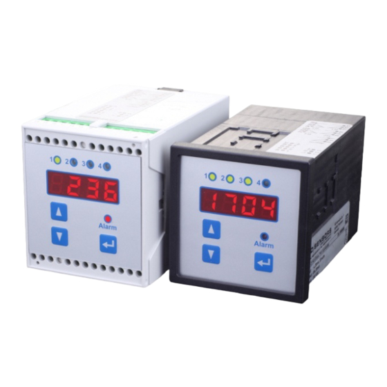
Multifunctional Process Transmitter CIT 400 / CIT 401
front panel housing
Important notes:
Please read this operating manual carefully before installing and starting up
the device.
This operating manual must be kept at an accessible location for further
use.
The device may only be installed, used and serviced by persons who are
familiar with this operating manual as well as with the applicable regulations
on occupational safety and accident prevention.
BD SENSORS GmbH
BD-Sensors-Straße 1
D - 95199 Thierstein
CIT 400
Telefon +49 (0) 92 35 / 98 11- 0
Telefax +49 (0) 92 35 / 98 11- 11
CIT 401
top-hat rail housing
www.bdsensors.de
info@bdsensors.de
Advertisement
Table of Contents

Subscribe to Our Youtube Channel
Related Manuals for BD Sensors CIT 400


Summary of Contents for BD Sensors CIT 400
- Page 1 Operating manual Multifunctional Process Transmitter CIT 400 / CIT 401 CIT 400 CIT 401 front panel housing top-hat rail housing Important notes: Please read this operating manual carefully before installing and starting up the device. This operating manual must be kept at an accessible location for further use.
-
Page 2: Table Of Contents
1.2 Target group ........................3 1.3 Symbols used ........................3 1.4 Safety notes........................3 1.5 Security note for the Ex-version of CIT 400 ..............3 1.6 Contents of packaging ...................... 4 2. Product identification ......................4 3. Installation ..........................5 3.1 General notes ........................ -
Page 3: General
Install the device in the currentless condition! 1.5 Security note for the Ex-version of CIT 400 When using the CIT 400 in intrinsic areas, the following additional demands must be fulfilled: For the installation, maintenance and cleaning of the device, you must absolutely ob-... -
Page 4: Contents Of Packaging
It is the responsibility of the user to verify whether the chosen device is suitable for the intended application and the existing environmental conditions. BD SENSORS does not assume liability for an incorrect selection and its consequences! The technical data listed for the explosion sector correspond to the values certified in the EC type-examination certificate. -
Page 5: Installation
CIT 400 / CIT 401 For identification of the firmware, the program version (e. g. P071) will appear for about 1 second in the display after starting up the device. Please hold it ready for inquiry calls. 3. Installation 3.1 General notes •... - Page 6 Before first connection, it is necessary to have a slight pressure on the screw of the clamping connection to ensure a safe opening and a correct connection. CIT 400: top-hat rail housing without Ex-protection top-hat rail housing with Ex-protection front panel housing without Ex-protection front panel housing with Ex-protection Fig. 3.1 Terminal clamps CIT 400...
-
Page 7: Installation Example
Fig. 4 CIT400 with 2-wire-sensor Fig. 5 CIT 400 with 3-wire-ultrasonic-sensor Example 3: CIT 400 as transmitter, when supplied with voltage signals from a pickup or to simulate an external sensor with voltage output at the CIT 400. Limit value... -
Page 8: Overvoltage Protection
CIT 400 / CIT 401 4. Overvoltage protection For effective protection of the process transmitters, it is necessary to protect power supply and mA outputs by using overvoltage protection devices. We recommend: - Data Pro 2x1 24 V/24 V for potential-free (galvanically isolated) data lines, 25 A leakage current as well as automatic self-control by failsafe diodes, which interrupt the current signal in case of error and cause an error message, given out by the process transmitter. -
Page 9: Menu Operation
The structure of the menu systems for the process transmitters CIT 400 and CIT 401 is identical. The CIT 401 deviates from the other by the gray marked menus, which are not available with CIT 400. - Page 10 CIT 400 / CIT 401 Display mode (measured value is displayed) Password activation Menu PAoF Scaled measure- Parameters of the Input signal Input signal Output signal Scaled value Output signal ment values display in mA in % in % with offset and...
-
Page 11: Menu List
CIT 400 / CIT 401 5.5 Menu list Menu level diSP - parameter of the display (mode) The menus "dIS1" to "dIS6" determine the display mode. Display - scaled measurement value dIS1 Indicates the scaled measurement value on the display. The indicated value may vary between 0.000 and 9999. - Page 12 CIT 400 / CIT 401 Menu level SinP - parameter of signal input (analogue input) The subordinate menu items are used to define the measurement span of the analogue input for 4 mA and 20 mA. Signal input - starting point of measuring range...
- Page 13 This menu level can be called up by pressing Enter like any other menu. After that, the respective relay must be selected. This can be achieved by selecting the numbers of the relay with the arrow keys. Confirm your selection with Enter (CIT 400 features 2 relays; CIT 401 features 4 relays).
- Page 14 CIT 400 / CIT 401 Menu level Aout - analogue output The settings for the analogue signal output are determined in the menu items. Analogausgang - output signal outY This menu defines the output signal range. You can choose between the following settings: 4-20 mA, 0-20 mA, 20-4 mA and 20-0 mA.
- Page 15 By changing the relays, both pumps will be activated on reaching the next turn-on point. With CIT 400, this function can be switched on and off. With CIT 401, values 2, 3, 4, and OFF can be set. The value gives the number of used relays for the changing.
-
Page 16: Error Handling
CIT 400 / CIT 401 6. Error handling Error messages Possible cause Error corrective - cable break between sensor on - check cable for damage analogue input - mechanical sensor damage and there- - exchange cable or sensor if fore interruption... -
Page 17: Interface Level Measurement
CIT 400 / CIT 401 Programming: Select the menu "dlS1" in the menu level "dlSP". Set the following values in the menu level "SInP": ZPIn (starting point of measuring range) EPIn (end point of pressure range) (decimal point position) Set the following values in the menu level "Aout":... -
Page 18: In Bounds / Out Of Bounds
CIT 400 / CIT 401 7.3 In bounds / out of bounds given: tank (max. level 7 m); medium: water; probe 4-20 mA; measuring range 10 m required: pen recorder on analogue output 4-20 mA, final peak of pen recorder 20 mA at 7 m;... -
Page 19: Changing Of Pumps
CIT 400 / CIT 401 7.4 Changing of pumps given: tank (max. level 7 m); medium: water; probe 4-20 mA; measuring range 10 m required: pen recorder on analog output 4-20 mA, final peak of pen recorder 20 mA at 7 m;... -
Page 20: Recalibration
CIT 400 / CIT 401 10. Recalibration During the life-time of the device, the offset may shift. As a consequence, a deviating signal val- ue in reference to the nominal pressure range starting point may be transmitted. The full scale may also shift. This would cause a signal value of the pressure switch to be transmitted that deviates from the nominal pressure range end point. -
Page 21: Appendix
CIT 400 / CIT 401 14. Appendix 14.1 Declaration of conformity www.bdsensors.com... -
Page 22: Ec Type-Examination For Cit 400 With Ex-Protection
CIT 400 / CIT 401 14.2. EC type-examination for CIT 400 with Ex-protection... - Page 23 CIT 400 / CIT 401 www.bdsensors.com...
- Page 24 The contents of this operating manual reflect the version available at the time of printing. It has been issued to our best knowledge and belief. However, errors may still be included. For incorrect statements and their consequences, liability cannot be assumed by BD SENSORS. – Technical modifications reserved –...
Need help?
Do you have a question about the CIT 400 and is the answer not in the manual?
Questions and answers