Table of Contents

Related Manuals for BD Sensors CIT 400


Summary of Contents for BD Sensors CIT 400
- Page 1 Operating manual CIT 400 Process Display BD SENSORS GmbH ID: BA_CIT400_E BD-Sensors-Straße 1 Telefon +49 (0) 92 35 / 98 11- 0 www.bdsensors.de D - 95199 Thierstein Telefax +49 (0) 92 35 / 98 11- 11 info@bdsensors.de Version: 10.2019.1...
-
Page 2: Table Of Contents
CIT 400 Table of contents 1. General and safety-related information on this operating manual ..........3 1.1 Symbols used ........................3 1.2 Staff qualification ........................ 3 1.3 Intended use ........................4 1.4 Limitation of liability and warranty ..................4 1.5 Safe Handling ........................4 1.6 Scope of Delivery ....................... -
Page 3: General And Safety-Related Information On This Operating Manual
CIT 400 1. General and safety-related information on this operating manual This operating manual enables safe and proper handling of the product, and forms part of the device. It should be kept in close proximity to the place of use, accessible for staff members at any time. -
Page 4: Intended Use
CIT 400 1.3 Intended use The multifunctional process transmitter CIT 400 has been especially developed for the supply and data acquisition of 2- and 3-wire-sensors with current signal. The micro-controlled device collect the signal of the sensor and show the measured value in a 4-digit LED-display. For sim- ple handling, the device features an extensive menu system with several menu levels. -
Page 5: Product Identification
CIT 400 2. Product identification The device can be identified by its type plate. It provides the most important data. By the order- ing code, the product can be clearly identified. For identification of the firmware, the program version (e. g. P074) will appear for about 1 second in the display after starting up the device. -
Page 6: Top-Hat Rail Mounting
CIT 400 3.2 Top-hat rail mounting The unit will be fastened by snapping it onto an installed DIN top-hat rail with a minimum length of 70 mm. 3.3 Front panel mounting The front panel housing has to be fastened by using 2 screw-in clamps. - Page 7 CIT 400 Standard: top-hat rail housing front panel housing Optionally: top-hat rail housing front panel housing Fig. 2 Terminal clamps www.bdsensors.de...
-
Page 8: Installation Example
Rel. 1 Display Writer Fig. 4 CIT 400 with 3-wire-ultrasonic-sensor Example 3: CIT 400 as transmitter, when supplied with voltage signals from a pickup or to simulate an external sensor with voltage output at the CIT 400. Limit value Sensor... -
Page 9: Overvoltage Protection
CIT 400 4. Overvoltage protection For effective protection of the process transmitters, it is necessary to protect power supply and mA outputs by using overvoltage protection devices. We recommend: - Data Pro 2x1 24 V/24 V for potential-free (galvanically isolated) data lines, 25 A leakage current as well as automatic self-control by failsafe diodes, which interrupt the current signal in case of error and cause an error message, given out by the process transmitter. -
Page 10: Operation
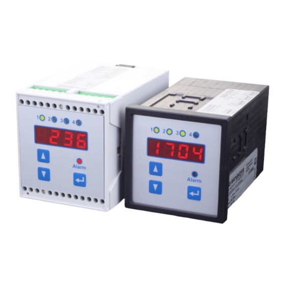
CIT 400 5. Operation 5.1 Operating and display elements standard option LED relay 1 LED relay 2 LED relay 2 LED relay 3 LED relay 1 LED relay 4 display "▲" - button LED Alarm "▼" - button Enter- button Fig. -
Page 11: Description Of The Menu Levels
CIT 400 5.3 Description of the menu levels There are 8 menu levels, which can be chosen separately. Paof = password protection diSP = display SinP = signal input (analogue input) = linearization rELn = contacts (relays) Aout = analogue output... - Page 12 CIT 400 Display mode (measured value is displayed) Password activation Menu PAoF Scaled measure- Parameters of the Input signal Input signal Output signal Scaled value Output signal ment values display in mA in % in % with offset and in mA...
-
Page 13: Menu List
CIT 400 5.5 Menu list Menu level diSP - parameter of the display (mode) The menus "dIS1" to "dIS6" determine the display mode. Display - scaled measurement value Indicates the scaled measurement value on the display. The indicated dIS1 value may vary between 0.000 and 9999. Confirm with Enter after select- ing "dIS1"... - Page 14 CIT 400 Menu level SinP - parameter of signal input (analogue input) The subordinate menu items are used to define the measurement span of the analogue input for 4 mA and 20 mA. Signal input - starting point of measuring range...
- Page 15 CIT 400 Menu level rELn - parameter of the contacts (relais) The menu items of this level are responsible for the limit value settings and the switching behav- iour of the relays. Since the menus for the relays have been conceived identically, the descrip- tion is the same for all menus.
- Page 16 CIT 400 Contacts - switch-off delay With this menu, you can define a switch-off delay within a range from 0 D1of to 100 seconds for the selected relay. Set the delay with the arrow keys D2of and confirm with Enter.
- Page 17 CIT 400 Menu level ALLG - unit parameter Menu level contains general unit parameters. Unit parameter - relay exchange With this menu, you can set the exchange of used relays if they reach a CHAn defined value. The background of this function is a pump exchange in order to achieve a regular pump load (capacity utilisation).
-
Page 18: Troubleshooting
CIT 400 6. Troubleshooting Danger of death from electric shock If malfunctions cannot be resolved, put the device out of service (proceed DANGER according to chapter 9 up to 11) In case of malfunction, it must be checked whether the device has been correctly installed me- chanically and electrically. -
Page 19: Programming Examples
CIT 400 7. Programming examples Please note that the display offset has to be set on "0" in the examples. Compare "dIS5" under "5.5 menu list". 7.1 Level measurement given: tank (max. level 7 m); medium: water; probe 4-20 mA; measuring range 10 m... -
Page 20: Interface Level Measurement
CIT 400 7.2 Interface level measurement given: tank (max. level 7 m); medium: water, probe 4-20 mA, measurement range 10 m required: pen recorder on analogue output 4-20 mA, final peak of pen recorder 20 mA at 7 m; the process transmitter has to indicate the max. filling level of the tank; relay 1 should have the function of a limit value switch (on = 6 m;... -
Page 21: In Bounds / Out Of Bounds
CIT 400 7.3 In bounds / out of bounds given: tank (max. level 7 m); medium: water; probe 4-20 mA; measuring range 10 m required: pen recorder on analogue output 4-20 mA, final peak of pen recorder 20 mA at 7 m;... -
Page 22: Changing Of Pumps
CIT 400 7.4 Changing of pumps given: tank (max. level 7 m); medium: water; probe 4-20 mA; measuring range 10 m required: pen recorder on analogue output 4-20 mA, final peak of pen recorder 20 mA at 7 m; the process transmitter has to indicate the max. filling level of the tank (7 m); relay 1 should have the function of a limit value switch (on = 6 m;... -
Page 23: Service / Repair
CIT 400 10. Service / repair Information on service / repair: www.bdsensors.de info@bdsensors.de Service phone: +49 (0) 92 35 / 98 11 0 10.1 Recalibration During the life-time of the device, the offset may shift. As a consequence, a deviating signal val- ue in reference to the nominal pressure range starting point may be transmitted. - Page 24 CIT 400 Notes: ____________________________________________________________________________ ____________________________________________________________________________ ____________________________________________________________________________ ____________________________________________________________________________ ____________________________________________________________________________ ____________________________________________________________________________ ____________________________________________________________________________ ____________________________________________________________________________ ____________________________________________________________________________ ____________________________________________________________________________ ____________________________________________________________________________ ____________________________________________________________________________ ____________________________________________________________________________ ____________________________________________________________________________ ____________________________________________________________________________ ____________________________________________________________________________ ____________________________________________________________________________ ____________________________________________________________________________ ____________________________________________________________________________ ____________________________________________________________________________ ____________________________________________________________________________ ____________________________________________________________________________ ____________________________________________________________________________ ____________________________________________________________________________ ____________________________________________________________________________ ____________________________________________________________________________ ____________________________________________________________________________ ____________________________________________________________________________ ____________________________________________________________________________ ____________________________________________________________________________ ____________________________________________________________________________ ____________________________________________________________________________ ____________________________________________________________________________ ____________________________________________________________________________ pressure and level Tel.:...
Need help?
Do you have a question about the CIT 400 and is the answer not in the manual?
Questions and answers