
Related Manuals for Crowcon Crowcon Gasmaster


Summary of Contents for Crowcon Crowcon Gasmaster
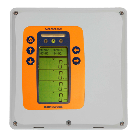
- Page 1 Crowcon Gasmaster 1 to 4 channel gas detection control panel Installation, Operation and Maintenance Manual M070010 Issue 2 October 2014...
- Page 2 Tel. +44 (0)1235 557700 Fax. +44 (0)1235 557749 www.crowcon.com Email: sales@crowcon.com © Copyright Crowcon Detection Instruments Ltd 2014 All rights are reserved. No part of the document may be photocopied, reproduced, or translated to another language without the prior written consent of...
-
Page 3: Table Of Contents
Crowcon Gasmaster Contents Contents 4.2 System Inhibit ....35 1. Introduction ..... 1 4.3 Detector Calibration . -
Page 5: Introduction
Gasmaster can also monitor flame detectors as well as Crowcon's ESU product. The status Warning of each input is displayed on a large, clear LCD Regular maintenance of any safety system is... -
Page 6: Instructions For Use As Part Of An Atex Approved System
1.3 Instructions for use as part EXAMPLES OF SAFE AREA APPARATUS of an ATEX approved system CROWCON GASMONITOR SYSTEM CROWCON GASMASTER SYSTEMS CROWCON VORTEX SYSTEMS Gasmaster is approved according to the 94/9/EC ATEX Directive when used as part of a system with... -
Page 7: Installation
2.8.1 Two wire 4-20mA devices configuration steps may require you to enter 2.8.2 Three wire 4-20mA devices Supervisor mode. Crowcon advises that personnel familiar with installing and commisioning gas and 2.8.3 mV bridge pellistor detectors. fire detection systems carry out this part. -
Page 8: Before Installation
Before carrying out any installation work, ensure that local regulations and site proce- dures are followed. Further advice is avail- able from Crowcon if required. Gasmaster is intended for use in non hazardous areas. Gas and fire detectors may be mounted in potentially flammable atmospheres using appro- ... -
Page 9: Mounting
Explosion-proof (Exd) devices Crowcon recommends the use of steel wire Figure 2.2 Gasmaster chassis plate with display PCB armoured (SWA) cable. Suitable explosion- board and batteries. -
Page 10: Installing Gas And Fire Detectors
– Screened cable with the screen terminated Fire detectors, inside the enclosure via a metal tag attached Crowcon recommends the use of twisted-pair to the gland. cable, screened with an overall protective sheath that is fireproof, for example, Pirelli –... -
Page 11: Connecting Input Devices
Crowcon Gasmaster Installation Mains supply Input modules Detector input Common relay terminals terminals Channel Display PCB relay connector terminals Link to chassis on non-I.S. systems only. Link to chassis on I.S. systems only. Audible/Visual Remote inhibit and 24 V dc supply. - Page 12 Figure 2.6 shows a typical wiring configuration 2.8.3. mV bridge pellistor detectors. for a 2-wire current sink detector for safe area Detectors such as Crowcon’s Xgard Type 3 or 4 use only. should be connected as shown. Refer to section 2.12.1 for instructions on detector set-up.
- Page 13 I.S. Earth P&F Z728 Zener Barrier Crowcon Part Number: C03317 Figure 2.7 Typical connections for 2 wire I.S. detector with Zener barrier, 4-20mA/Fire input module Set channel link to SINK (see figure 2.5) and configuration to DET4-20 SINK (see Menu System Overview section, page 25 and 33.
- Page 14 Inputs are activated P&F Z728 Zener Barrier tors fitted to the ESU should be cabled separately Crowcon Part Number: C03317 when pulled down to 0 V, the open circuit volt- to the appropriate input channels on the age is 5 V dc.
-
Page 15: Connecting Output Devices
CONNECTIONS FOR A AUDIBLE VISUAL 0V (-VE) SWITCHED ALARM 1 A/V DEVICE Crowcon recommends screened cables for con- BEACON necting remote switches. The screen should be terminated at the appropriate ‘SCR’ terminal. Link Settings for 24V Alarm Devices... - Page 16 Installation Crowcon Gasmaster output terminals may be set to either 12 V dc or not activate). 4-20 mA flame detectors will activate two levels of alarm as per a gas detector. 24 V dc by moving the ‘V AV’ link. Refer to Figure 2.5 on page 7 for details...
-
Page 17: Applying Power
Gasmasters except the last unit on the line. times. A Modbus specification document is available Note: your Gasmaster is supplied pre-config- from Crowcon on request. ured, refer to the Specification and Inspection Certificate provided with your system. If no chan- The RS-485 terminals on Gasmaster systems... -
Page 18: Battery Back-Up Times
001 which can be downloaded from the Partners Note: The internal batteries may not be charged section of the Crowcon website. Alternatively con- efficiently when Gasmaster is powered from an tact customersupport@crowcon.com. external dc supply, and therefore the back-up function may not work if the external supply fails Please contact Crowcon for further advice. - Page 19 Crowcon Gasmaster Installation From the Supervisor menu, scroll down 2.12.2. Zero adjustment and to Inhibit and press Continue . Select calibration All and press Continue . Use the Up Calibration must be carried out separately on or Down button to set inhibit to individual gas detectors on Gasmaster.
- Page 20 Installation Crowcon Gasmaster Calibrate Wizard. Ensure the channels are connected directly as a 4-20 input, and may have various alarm levels to indicate UV or IR activation inhibited prior to applying gas. (please refer to the instructions supplied with the 5.
-
Page 21: Operation
Crowcon Gasmaster Operation 3. Operation Every Gasmaster system is pre-configured by Crowcon, please refer to the Specification and #1=CH4 #2=O2 Inspection Certificate provided with the product for configuration details. This section describes #3=H2S #4=FIRE the operation of pre-configured units, and includes procedures for altering settings. - Page 22 Operation Crowcon Gasmaster triggered, and will remain in a steady 'on' state when the accept/reset button Channel number pressed. The LED bar will flash again if a new reading Fault alarm is triggered. Warning Operator Panel Buttons Channel Inhibit Units...
-
Page 23: Gasmaster Start Up Sequence
Crowcon Gasmaster Operation Faults Lists the fault conditions present GASMASTERII Warnings = Software version number Lists the warning conditions present View View current status of relays, outputs, detector inputs, power supply and con- figuration ...Detecting Gas, Sav Action ... -
Page 24: Using The Menu System
Operation Crowcon Gasmaster First the Local Service telephone number is dis- Menu wizards played followed by the customer identity display. Wizards are an extension of the menu system to After 10 seconds the serial number will automati- guide the user through a process such as calibra- cally be displayed on the next screen (for approxi- tion. -
Page 25: Using The Control Panel In
Warning alpha-numeric list. To enter ‘ZZZ’ use Crowcon strongly recommends that remote the Up and Down buttons to inhibit switches be key operated only, and... -
Page 26: In The Event Of An Alarm
Operation Crowcon Gasmaster Note: pressing the Accept/Reset button to clear Note: Double click the Up or Down alarms from conventional fire detectors removes button to move to the top or bottom power from the smoke/heat detector for 2 sec- of the alphabet list. To enter numbers or onds to reset the device (this ‘fire reset time’... -
Page 27: In The Event Of A Fault
Saver will be enabled if the channel is not communications port is required if Gasmaster PC inhibited). Note: the channel will remain in is to be used, contact Crowcon for details. Pellistor Saver Disabled mode until it is manu- ally re-enabled or the 15-minute time-out 3.11.1. - Page 28 Loaded default settings System has returned to standard configuration settings. Re-configure using the Supervisor menu. Common relay fail Coil fault detected. Contact Crowcon 9, 10, 11 Chan #1 relay fail Channel relay coil fault detected. 12 to 19 Contact Crowcon.* ESU #1 stalled! ESU sampling device has stopped.*...
- Page 29 Crowcon Gasmaster Menu system overview Press CONTINUE Faults Warnings View Action Supervisor Faults Menu Warnings View Menu Action Menu Supervisor Menu Menu List of faults Relay com stat Display contrast present Relay chan stat Control panel List of warnings Password...
- Page 30 Menu system overview Crowcon Gasmaster Warnings menu (lists warnings present on the system) Menu Item Values Description Codes (as shown on display) No warnings (end of list) No warnings are present. Warnings Supervisor mode System configurations may be changed. Global inhibit All input channels are inhibited.
- Page 31 Crowcon Gasmaster Menu system overview View menu (shows system status and configuration, but does not allow changes to be made.) Menu Item Values Description (as shown on display) L1 = Level 1. Relay com stat Alarm L1 common Values = No alarm...
- Page 32 Menu system overview Crowcon Gasmaster Actions menu (allows basic tests and adjustments.) Menu Item Values Description (as shown on display) Audio Visual: Drives Audible Visual alarm terminals to test external Audio visual Test alarm? audible visual alarms Values = Testing beacon Beacon output becomes active for 3 seconds, followed by;...
- Page 33 Crowcon Gasmaster Menu system overview Supervisor menu (allows system tests to be performed, and configurations to be changed. A pass word is required to enter this mode, see section 3.7 for details.) Menu Item Values Description (as shown on display) Inhibit Inhibits all input channels when selected.
- Page 34 Menu system overview Crowcon Gasmaster Supervisor menu (allows system tests to be performed, and configurations to be changed. A pass cont. word is required to enter this mode, see section 3.7 for details.) Menu Item Values Description (as shown on display) User action Apply gas and calibrate the detector.
- Page 35 Crowcon Gasmaster Menu system overview Supervisor menu (allows system tests to be performed, and configurations to be changed. A pass cont. word is required to enter this mode, see section 3.7 for details.) Menu Item Values Description (as shown on display) No alarms will be activated on Gasmaster.
- Page 36 Menu system overview Crowcon Gasmaster Supervisor menu (allows system tests to be performed, and configurations to be changed. A pass cont. word is required to enter this mode, see section 3.7 for details.) Menu Item Values Description (as shown on display)
- Page 37 Crowcon Gasmaster Menu system overview Supervisor menu (allows system tests to be performed, and configurations to be changed. A pass cont. word is required to enter this mode, see section 3.7 for details.) Menu Item Values Description (as shown on display)
- Page 38 Menu system overview Crowcon Gasmaster Supervisor menu (allows system tests to be performed, and configurations to be changed. A pass cont. word is required to enter this mode, see section 3.7 for details.) Menu Item Values Description (as shown on display)
-
Page 39: Maintenance
It is essential that any safety system such enter Supervisor mode and set the relevant detec- as Gasmaster is routinely checked. Crowcon tor Type to Unused (see page 33). The channel display will be no longer shown, and the power offer service contracts to ensure that this supply will be removed from the detector. -
Page 40: Detector Calibration
Crowcon approved personnel. Please contact Installation, Operating and Maintenance Instruc- Crowcon for details of your nearest service centre. tions provided with each detector. 4.6 Event logging 4.4 Changing Batteries... -
Page 41: Adding An Input Module
GasMaster Adding an input module 5. Adding an input module The 4-channel version of Gasmaster may be sup- plied pre-fitted with between one and four input modules of the following types: • 4-20 mA/Fire module for 4-20 mA type detectors, conventional smoke/heat detec- tors or ESU. -
Page 42: Appendix A: Specifications
(4-20 mA or digital contact signal). For use with one Crowcon ESU fan For use with one to four Crowcon Environmental (ie ‘sampling device’ changes to ‘fan’). -
Page 43: Appendix B: Spare Parts And Accessories
Crowcon Gasmaster Appendix B: Spare parts and Accessories Appendix B: Spare Parts and Accessories Part No. Description Comment E01875 12V 1.2Ah battery 2 required E07534 Battery fuse assembly Assembly with fuse, fuse holder and loom M05897 Service card Replacement service cards, minimum quantity 10... -
Page 44: Appendix C: Display Characters
Appendix C: Display characters Crowcon Gasmaster Appendix C: Display characters Message display area characters Channel display characters When editing strings of text for passwords, NB: The following characters represent those detector location or system identity, the following which can be shown on the channel display area characters are available: to represent detector types. -
Page 45: Warranty Statement
Instrument serial number(s). Reason for return. Crowcon reserves the right to apply a handling and carriage charge whereby units returned as faulty, are Obtain a Returns form for identification and trace- found to require only normal calibration or servicing, ability purpose. -
Page 46: Regional Addresses
Regional addresses Crowcon Gasmaster Regional addresses...
Need help?
Do you have a question about the Crowcon Gasmaster and is the answer not in the manual?
Questions and answers