Table of Contents
Advertisement
Available languages
Available languages
Advertisement
Table of Contents

Related Manuals for Mac allister LL6A


Summary of Contents for Mac allister LL6A
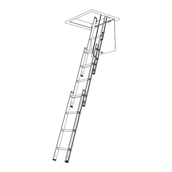
- Page 1 EASY STOW ALUMINIUM LOFT LADDER - 3 SECTION ÉCHELLE ESCAMOTABLE À FAIBLE ENCOMBREMENT, 3 PLANS LL6A EAN 3663602910626 WARNING : Please read the instructions before using the loft ladder. AVERTISSEMENT : Lisez les consignes avant d’utiliser l’échelle.
- Page 3 get started... Let’s These instructions are for your safety. Please read through them thoroughly before use and retain them for future reference. started Getting Safety Safety instructions Your product more detail Installation and operating instructions Commençons … Ces instructions sont pour réalisées votre sécurité. Nous vous remercions de prendre le temps de les lire attentivement avant l’utilisation du produit.
- Page 4 Ensure installation is Avoid electrical hazards. in accordance with the Check clearances at top and manufacturer’s instructions. access. Ensure you have read all Éviter tout danger instructions and safety labels électrique. Veillez à ce qu’il and use ladder in accordance y ait assez d’espace en haut with these.
- Page 5 Safety Instructions Before commencing the installation or operation of this product, read these instructions carefully and completely, noting in particular the instructions regarding safety (below). This ladder should never be used as a free standing leaning ladder. Do not attempt to climb your loft ladder until installation is complete. Use a second ladder to gain access to the loft while carrying out the work.
- Page 6 Safety Instructions Please check you have all components listed (tick boxes) Before commencing the installation or operation of this product, read these instructions carefully and completely, noting in particular the instructions regarding safety (below). This ladder should never be used as a free standing leaning ladder. Do not attempt to climb your loft ladder until installation is complete.
- Page 7 Adapting the trapdoor firmly shut. If the trapdoor does not hinge downwards, The loft ladder is suitable for a loft opening let flush or is not hinged at all, you will need to adapt or replace into the ceiling, having a hinged trapdoor opening it so that it does.
- Page 8 Secure the travel stop ring (A2) using screw (A7). Secure the catch assembly with M12 nut (A4) 45° ensuring the nut is tightened sufficiently to allow the catch to rotate freely without any looseness. Fixing the Location Bracket When turned to the correct position, the catch lever will engage in the location bracket to hold the trapdoor shut.
- Page 9 Slide the hinge guides (B1 & B2) onto the rear frame stiles. The brackets should be positioned outwards, with the double holed half uppermost (see diagram). Slide all the way up to the factory–fitted permanent top stops. Do not replace the plastic end tips at this stage (see later at step 6.5).
- Page 10 Installing the Ladder N.B. The ladder should be installed on the same side of the trap as the trapdoor hinges. With the ladder preferably centred in the opening, and the trapdoor hanging down, locate the hinge guide bracket arms (B1 & B2) on the top edge of the loft hatch frame (see diagram).
- Page 11 Locate the power arm linkage plates either side of pivot tip (F4)/ladder stile and align all holes. 8.10 Secure the stile to the linkage plates using bolt (F5), washers (F6), nut and nut cap (F7 & F8). Ensure bolt (F5) and nut (F7) are tightened sufficiently to allow the linkage to freely rotate without any looseness.
- Page 12 10.3 Locate the stowing hook/key (E3) over and at the centre of the REAR ladder section bottom rung and steadily pull the ladder outward and downward until both top stops reach and make contact with the hinge guides. 10.4 Retract both right-hand side catches ‘C’ & ‘D’ (blue) and rotate both catch levers upwards into the locked open position (see diagram).
- Page 13 Consignes de sécurité Avant de commencer l’installation et l’utilisation de ce produit, lisez cette notice attentivement et intégralement, soyez particulièrement attentif aux consignes de sécurité (ci-dessous). Cet escalier ne doit jamais être utilisé comme une échelle d’appui autoportante. N’essayez pas de monter sur votre escalier escamotable tant que son installation n’est pas terminée. Utilisez une autre échelle pour accéder au grenier pendant le travail d’installation.
- Page 14 Consignes de sécurité Vérifiez qu’il ne manque aucune pièce (cochez les cases) Avant de commencer l’installation et l’utilisation de ce produit, lisez cette notice attentivement et intégralement, soyez particulièrement attentif aux consignes de sécurité (ci-dessous). Cet escalier ne doit jamais être utilisé comme une échelle d’appui autoportante. N’essayez pas de monter sur votre escalier escamotable tant que son installation n’est pas terminée.
- Page 15 Adapter la trappe L’escalier escamotable convient pour une ouverture charnière ne s’ouvre pas vers le bas ou si elle ne comporte d’accès à un grenier au ras du plafond pourvue d’une pas de charnière, vous devez la modifier ou la remplacer trappe à...
- Page 16 Fixez la bague de butée (A2) avec la vis (A7). Fixez le loquet avec l’écrou M12 (A4) en veillant à ce que l’écrou soit suffisamment serré pour maintenir le loquet sans gêner sa rotation. 45° Fixer la gâche Lorsque le pêne est tourné dans la position appropriée, il rentre dans la gâche et maintient la trappe fermée.
- Page 17 Insérez les guides de charnière (B1 et B2) sur les montants du plan arrière. Les pattes de fixation doivent être positionnées vers l’extérieur avec les pattes à deux trous en haut (voir le schéma). Faites-les glisser jusqu’aux butées supérieures permanentes installées en usine. Ne réassemblez pas les embouts en plastique pour l’instant (voir l’étape 6.5 ci-après).
- Page 18 Fixer l’escalier Remarque : L’escalier doit être fixé du même côté de la trappe que les charnières de la trappe. Avec l’escalier centré dans la trémie et la trappe pendant vers le bas, positionnez les pattes de fixation des guides de charnières (B1 et B2) sur le bord supérieur du cadre de la trémie (voir le schéma).
- Page 19 Placez les plaquettes d’assemblage du bras à ressort de chaque côté de l’extrémité de rotation (F4)/montant de l’escalier et alignez tous les trous. 8.10 Fixez les plaquettes d’assemblagea sur le montant avec la vis (F5), les rondelles (F6), l’écrou et l’écrou borgne (F7 et F8).
- Page 20 10.3 Placez le crochet de fermeture (G3) sur le centre de la marche inférieure du plan ARRIÈRE de l’escalier et tirez sans à-coups l’escalier vers l’extérieur et le bas jusqu’à ce que les deux butées supérieures atteignent les guides de charnière.
- Page 21 Product contains / Le produit contient 37093 PETE OTHER...
- Page 24 B&Q plc, Chandlers Ford, Hants, SO53 3LE United Kingdom www.diy.com Castorama France C.S. 50101 Templemars 59637 Wattignies CEDEX www.castorama.fr macallister@castorama.fr LF37093 Rev 1 04/16...
Need help?
Do you have a question about the LL6A and is the answer not in the manual?
Questions and answers
I **** unable to lower the ladders as they seem to be jammed at the arm mechanism
The manual does not provide specific instructions for fixing a jammed arm mechanism on the Mac Allister LL6A ladder. However, you can try the following steps based on general ladder operation:
1. Check for Obstructions – Ensure no debris or objects are blocking the mechanism.
2. Retract Catches – Try retracting the right-hand side catches (‘C’ & ‘D’) and rotating the catch levers upwards into the locked open position.
3. Inspect for Misalignment – Verify that all components, including hinge guides and top stops, are properly aligned.
4. Apply Gentle Pressure – Carefully pull or push the mechanism while ensuring catches and levers are engaged correctly.
5. Lubricate Moving Parts – Use a light lubricant on hinges and moving connections if they appear stiff.
6. Check for Damage – If components are bent or broken, replacement parts may be required.
If the issue persists, consult the manufacturer or a professional for further assistance.
This answer is automatically generated