
Related Manuals for suprema OM-120


Summary of Contents for suprema OM-120
- Page 1 INSTALLATION GUIDE OM-120 English Version 1.00 EN 101.00.OM120 V1.00A...
-
Page 2: Table Of Contents
Contents Safety Instructions ..................3 Components ...................... 4 Front Side ......................5 LED Status ..............................6 Installation Example ..................7 Dimensions ......................8 Installation ......................9 Connections ....................10 Power ................................10 RS-485 ................................10 Relay ................................11 AUX ................................12 Product Specifications ................. -
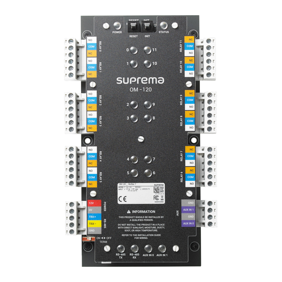
Page 3: Safety Instructions
Safety Instructions Safety Instructions Please read the following instructions carefully before using the product. This information is important for ensuring the safety of the user and for preventing damage to the user's property. Warning Violation of the instructions may cause serious injury or death. Installation Instructions Do not install the product in direct sunlight or in a location that is damp or dusty. -
Page 4: Components
Components Components Mounting screws (12) Spacer OM-120 Drilling Template... -
Page 5: Front Side
Relay 5 Relay 6 Relay status LED (4, 5, 7, 6) Power AUX1 AUX0 RS-485 Termination Switch Communication status LED (RS-485, AUX) Note • Press INIT button to reset OM-120 interworking with a device and then connect to another device. -
Page 6: Led Status
Front Side LED Status Status POWER Solid red: Power is on. Solid green: Connected with the secure session. Solid blue: Disconnected from the master device. STATUS Solid pink: Upgrading the firmware. Solid yellow: RS-485 communication error due to different encryption key or OSDP packet loss. Solid sky blue: Connected without the secure session. -
Page 7: Installation Example
Installation Example OM-120 is an expansion module for floor access control. Combined with Suprema device and BioStar 2, a single module can control 12 floors. When the OM-120 is connected as daisy chain via RS-485, you can control up to 192 floors per elevator. -
Page 8: Dimensions
Dimensions Dimensions (Unit: mm) -
Page 9: Installation
Installation OM-120 can be mounted in the cabinet or elevator control panel. With the mounting screws, fix the spacer firmly onto the surface where OM-120 is to be installed. With the mounting screws, mount the OM-120 firmly onto the spacer. -
Page 10: Connections
If it is installed in the middle of the chain, the performance in communicating will deteriorate because it reduces the signal level. • Up to 31 modules can be connected to the master device. Termination (120Ω) Access Controller OM-120 Termination RS-485 TRX+ RS-485 TRX-... -
Page 11: Relay
Connections Relay • Relay connection may vary depending on the elevator. Please consult your elevator installer for details. • Each relay has to be connected to the corresponding floor. • Use the figure below as an example. Elevator Control Panel Elevator Floor Button... -
Page 12: Aux
Connections • The dry contact output or tamper can be connected.. Tamper... -
Page 13: Product Specifications
Product Specifications Product Specifications Category Feature Specification Cortex M3 72MHz Memory Flash 128KB, SRAM 20KB Multi-color • POWER 1 ea • RELAY 12 ea • RS-485 2 ea • AUX IN 2 ea General • STATUS 1 ea Operating temperature -20°C ~ 60°C Storage temperature -40°C ~ 70°C... -
Page 14: Fcc Compliance Information
FCC Compliance Information FCC Compliance Information THIS DEVICE COMPLIES WITH PART 15 OF THE FCC RULES. Operation is subject to the following two conditions: (1) This device may not cause harmful interference, and (2) This device must accept any interference received, including interference that may cause undesired operation. NOTE: This equipment has been tested and found to comply with the limits for a Class A digital device, pursuant to Part 15 of the FCC Rules. -
Page 15: Appendix
This document provides the information pertaining to Suprema's products. • The right of use is granted only to the products that are covered by the sales agreement and conditions guaranteed by Suprema. Any license of intellectual property that is not dealt within this document is not granted. - Page 16 www.supremainc.com www.supremainc.com...
Need help?
Do you have a question about the OM-120 and is the answer not in the manual?
Questions and answers