Table of Contents
Advertisement
Quick Links
Advertisement
Table of Contents

Subscribe to Our Youtube Channel
Related Manuals for suprema OM-120


Summary of Contents for suprema OM-120
- Page 1 Output Module INSTALLATION GUIDE Version 1.01 English EN 101.00.OM-120 V1.01A...
-
Page 2: Table Of Contents
CONTENTS Safety information Product Specifications Instructional icons Dimensions Introduction FCC compliance information Components Accessory Appendices Name of each part Disclaimers LED Indicator Copyright Notice Installation example Installation Power Connection RS-485 Connection Relay Connection Using the Output Module with the enclosure... -
Page 3: Safety Information
Safety information Please read this safety instructions before you use the product to prevent injury to yourself and others and to prevent property damage. The term 'product' in this manual refers to the product and any items provided with the product. Instructional icons Warning: This symbol indicates situations that could result in death or severe injury. - Page 4 Safety information Caution Installation Do not install the power supply cable in a location where people pass by. • This may result in injury or product damage. Do not install the product near magnetic objects, such as a magnet, TV, monitor (especially CRT), or speaker. •...
-
Page 5: Introduction
Introduction Components POWER STATUS RESET INIT OM 120 AUX IN 1 TRX+ TRX- AUX IN 0 TERM Output Module Drilling Template (OM-120) Fixing screw x12 Spacer x6 • Components may vary according to the installation environment. -
Page 6: Accessory
Introduction Accessory You can use the Output Module with the enclosure (ENCR-10). The enclosure is sold separately, and you can install two Output Modules in one enclosure. The enclosure includes a power status LED board, power distribution board, power supply, and tamper. To learn how to install the Output Module in the enclosure, refer to Using the Output Module with enclosure. -
Page 7: Name Of Each Part
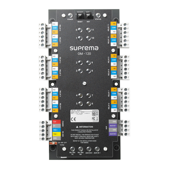
Introduction Name of each part RESET button INIT button Power status LED Operation status LED POWER STATUS RESET INIT Relay 0 Relay 11 Relay 1 Relay 10 Relay status LED (0, 1, 11, 10) OM 120 Relay 2 Relay 9 Relay 3 Relay 8 Relay status LED... -
Page 8: Led Indicator
OM-120 is an expansion module for floor access control. Combined with Suprema device and BioStar 2, a single module can control 12 floors. When the OM-120 is connected as daisy chain via RS-485, you can control up to 192 floors per elevator. -
Page 9: Installation
Installation Output Module can be mounted in the enclosure or elevator control panel. • To learn how to install the Output Module in the enclosure, refer to Using the Output Module with the enclosure. Fix a spacer on the position to mount Output Module using a fixing screw. Fix the product on top of the fixed spacer firmly using a fixing screw. -
Page 10: Rs-485 Connection
• Up to 31 modules can be connected to the master device. Terminating resistance (120Ω) AUX IN 1 TRX+ TRX+ TRX- AUX IN 0 TRX- TERM TERM Access Controller OM-120 Termination RS-485 RS-485 TRX+ TRX-... -
Page 11: Relay Connection
Installation Relay Connection • Relay connection may vary depending on the elevator. Please consult your elevator installer for details. • Each relay has to be connected to the corresponding floor. • Use the figure below as an example. Elevator Control Panel Elevator Floor Button... -
Page 12: Aux
Installation The dry contact output or tamper can be connected. Tamper AUX IN 1 AUX IN 0... -
Page 13: Using The Output Module With The Enclosure
Installation Using the Output Module with the enclosure The Output Module can be installed inside the enclosure (ENCR-10) for physical and electrical protection. The enclosure includes a power status LED board, power distribution board, power supply, and tamper. The enclosure is sold separately. - Page 14 Installation Installing the Output Module in the enclosure Check the position to install the Output Module in the enclosure. You can install two Output Modules in one enclosure. After positioning the Output Module in the enclosure, fix it with the fixing screws. POWER RS-485 RELAY 0...
- Page 15 Installation Power and AUX Input Connection You can connect an Uninterruptible Power Supply (UPS) to prevent power failure. And a power failure detector or a dry contact output can be connected to the AUX IN terminal. AUX IN 1 TRX+ TRX- AUX IN 0 TERM...
- Page 16 RELAY 5 POWER RS-485 RELAY 0 RELAY 1 RELAY 2 RELAY 3 RELAY 4 RELAY 5 POWER RS-485 RELAY 0 RELAY 1 RELAY 2 RELAY 3 RELAY 4 RELAY 5 • For more information, contact the Suprema technical support team (support.supremainc.com).
-
Page 17: Product Specifications
Product Specifications Category Feature Specification Model OM-120 Cortex M3 72 MHz Memory 128KB Flash, 20KB SRAM Multi-color • POWER - 1 • RELAY - 12 • RS-485 TX - 1 • RS-485 RX - 1 • AUX IN - 2 General •... -
Page 18: Dimensions
Product Specifications Dimensions (Unit: mm) * The tolerance is ±0.3 mm. POWER STATUS RESET INIT OM 120 AUX IN 1 TRX+ TRX- AUX IN 0 TERM... -
Page 19: Fcc Compliance Information
• Modifications: Any modifications made to this device that are not approved by Suprema Inc. may void the authority granted to the user by the FCC to operate this equipment. -
Page 20: Appendices
Information in this document is provided in connection with Suprema products. • The right to use is acknowledged only for Suprema products included in the terms and conditions of use or sale for such products guaranteed by Suprema. No license, express or implied, by estoppel or otherwise, to any intellectual property is granted by this document. - Page 21 QR code. http://www.supremainc.com/en/about/contact-us.asp © 2021 Suprema Inc. Suprema and identifying product names and numbers herein are registered trade marks of Suprema, Inc. All non-Suprema brands and product names are trademarks or registered trademarks of their respective companies.
Need help?
Do you have a question about the OM-120 and is the answer not in the manual?
Questions and answers