Table of Contents
Advertisement
Quick Links
Advertisement
Table of Contents

Related Manuals for Infratek 106A


Summary of Contents for Infratek 106A
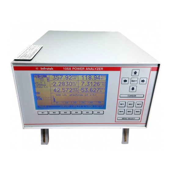
- Page 1 USERS MANUAL 106A SINGLE- AND THREE PHASE POWER ANALYZER Infratek...
-
Page 2: Table Of Contents
TABLE OF CONTENTS Safety Warnings Introducing the High Speed Power Analyzer Options and Accessories Specifications Mathematical Definitions used by the Power Analyzer Getting Started Front Panel and Rear Panel Adjusting the Optimal Viewing Angle Line Power Turning the Power Analyzer On Using the Function Keys Selecting a Measurement Range Taking Some Basic Power Measurements... - Page 3 Scaling of Current- and Voltage Inputs 5.13 Saving Instrument Settings 5.13.1 This is How you Save Your Desired Instrument Setting 5.13.2 This is How the 106A Starts Up in the Desired Configuration Operating the Power Analyzer Using the Computer Interface Introduction Local and Remote Operations...
-
Page 4: Safety
SAFETY Before using the Power Analyzer, read the following safety information carefully. In this manual „WARNING“ is reserved for conditions that pose hazards to the user; „CAUTION“ is reserved for conditions that may damage your instrument. Turn off power in the circuit to be measured. ... -
Page 5: Warnings
WARNINGS Before reading the manual or before using this instrument read carefully the warnings below and make sure you understand them. WARNING: Line Power To avoid shock hazard, connect the instrument power cord to a power receptacle with earth ground. ... - Page 6 INTRODUCING THE POWER ANALYZER WARNING Read the „Power Analyzer Safety“ in section 1 of this manual before using the instrument. This 1- and 3-phase Power Analyzer is designed for bench-top, field service, and system application. Some features provided by the Power Analyzer are: Large, blue LCD monitor, 120 x 64mm (240x128 pixels).
-
Page 7: Options And Accessories
OPTIONS AND ACCESSORIES Option 01 contains the RS-232 serial interface, the Centronics printer output, and the Windows Operating Software. Option 02 contains the RS-232 serial interface, the Centronics printer output, the IEEE-488 interface, and the Windows Operating Software. The IEEE-488 interface complies with the 488.1 and the 488.2 (1987) standard. -
Page 8: Specifications
ACS5: Shunt input connector. ACS6: Service Manual ACS7: Rack Mounting Kit ACS8: Official Calibration Certificate from SCS (SCS: Swiss Calibration Service) ACS10: RS-232 / USB Adapter ACS11: RS-232 / Ethernet Adapter SPECIFICATIONS This section defines the performance of the Power Analyzer. The user must be aware that exposure of the Power Analyzer current inputs to their maximum value will result in additional measurement errors. - Page 9 Voltage 8 ranges: 0.3 V, 1 V, 3 V, 10 V, 30 V, 100 V, 300 V, 1000 V Frequency range DC, 0.1 Hz – 1 MHz Crest Factor 3:1 at 50 % full scale (fs) Input Impedance 1 MOhm Common Mode 50 Hz/100 kHz 160 dB/100 dB...
- Page 10 Dimension H x W x D; weight 150 x 235 x 320 mm; 4 kg Options IEEE-488-2, RS232, Centronics printer output 4 programmable analog output; single-, sum-, or average values 0 - ±5 V, accuracy 0.2 % 4 analog inputs 0 - ±5 V, input impedance 200 kΩ 0 - ±5 V, accuracy 0.2 % 4 analog inputs 0 - ±10 V, input impedance 200 kΩ...
-
Page 11: Mathematical Definitions Used By The Power Analyzer
MATHEMATICAL DEFINITIONS USED BY THE POWER ANALYZER NOTE: RMS-, rectified mean-, mean-, maximum-, minimum-, and peak-to-peak value apply to current and voltage. Energies apply to real-, apparent-, and reactive power. Charge applies to rectified mean current only. Total harmonic distortion applies to current and voltage. -
Page 12: Getting Started
GETTING STARTED This section explains how to prepare the Power Analyzer for operation, discusses general operating features, and explains some common measurements. FRONT PANEL AND REAR PANEL The front panel in figure 4.1 shows the graphics display in the center and the control keys to the right of the front panel. -
Page 13: Adjusting The Optimal Viewing Angle
The rear panel shown in figure 4.2 contains the input terminals on the right hand side. The Hi- and Lo-voltage terminals are at the top. Below are the current input terminals, two red terminals for 5A and 30A with one common Lo terminal. The shunt input is equipped with a short connector. -
Page 14: Line Power
LINE POWER WARNING To avoid shock hazard, connect the Power Analyzer line cord to a receptacle with earth ground. Plug the line cord into the connector on the rear of the instrument. It will operate on any line voltage between 85V ac and 265V ac without adjustment, and any frequency between 50 and 400Hz. -
Page 15: Selecting A Measurement Range
These menus are dynamically changing, depending on the cursor position and other action you may take. SELECTING A MEASUREMENT RANGE When turning on the Power Analyzer the range selection is automatic. This is indicated by the range annunciator’s on the left hand side of the display, e.g. 1A A / 300mV A. - Page 16 The user should be well aware of the fact, that switching off inductive loads may generate extremely fast and high voltage transients exceeding above limits. To measure voltage, current, power and related quantities in a 3-phase circuit connect the test leads as shown in figure 4.3 and described below. Fig.
- Page 17 Switch on the Power Analyzer (it will be in automatic ranging). Select the correct current input IN 5A or IN 30A as described in 4.6. Turn on power to the load to be measured. The Power Analyzer will automatically select the voltage range and displays ...
-
Page 18: Operating The Power Analyzer From The Front Panel
OPERATING THE POWER ANALYZER FROM THE FRONT PANEL This section explains how to operate the instrument from the front panel. INTRODUCTION This Power Analyzer is a very advanced measuring system, equipped with features not known to similar instruments. For example, you can select dc- or ac-coupling for individual quantities, you can choose those quantities you want to integrate, you can combine meter mode and graphics mode, you can obtain harmonic analysis while the Power Analyzer is running in the meter mode. -
Page 19: Current Input Selection
Power Analyzer will give you direct read out in ampere for your shunt or your current clamp (with voltage output). Finally, the 106A also contains a low current 1A input via shunt connector and current Lo. To use this input proceed as follows: select IN 5A input (ranges 15mA, 50mA, 150mA, 500mA, 1.5A, 5A, 15A). -
Page 20: Selecting Synchronization
Move now the cursor to the desired range and press the SET-key again to select that range. The current input is now in manual ranging indicated by the M in the range annunciator. In similar manner a voltage range is selected. Once you have selected a current range the current input of the power analyzer is in manual ranging. -
Page 21: Fast Response Power Analyzer (Z-Version)
To select the measurement time move the cursor to the measurement time annunciator and press the SET-key. The pull-down menu gives you five choices. Select the one you need by moving the cursor to the desired position. Press the SET-key to select the desired measurement time. 5.6.1 FAST RESPONSE POWER ANALYZER (Z-VERSION) In spite of fast response these instruments maintain excellent accuracy. -
Page 22: Changing The Display Configuration, Transformer Testing, Motor Testing
CHANGING THE DISPLAY CONFIGURATION, TRANS- FORMER TESTING, MOTOR TESTING You have the choice of selecting 8 current values: rms, mean, rectified mean, crest factor, minimum, maximum, peak-to-peak, and form factor. 8 values four voltage, four power related quantities, frequency, three energies, charge, and harmonics of current , voltage, and power. -
Page 23: Changing The Harmonic Number
Measured and computed data can be stored in excel compatible files. Motor Testing For motor testing Option 07/M reads torque, speed, and other values from the rear panel analog inputs. These inputs can be scaled to obtain torque in Nm and speed in rpm (rotation per minute). -
Page 24: Auto Range Selection
While the Power Analyzer is in HOLD you can inspect every measurement value by altering the number field, e.g. you can step through every harmonic value of current, voltage, or power; you can change the graphic area and view the harmonic bar graph of current, voltage, or power;... - Page 25 Menu FFTi: Pressing the menu control F2 (M2) selects the harmonic bar graph of current. (Note: The size of the graphic area can be changed at any time.) The horizontal axis shows the harmonic numbers from 0-59, N=zero being the DC-value and N=1 being the fundamental of the current. The vertical axis shows the magnitude of the harmonic currents.
-
Page 26: Short Time Integrator
For longtime energy computation refer to the section ENERGY COMPUTATION. 5.11 ENERGY COMPUTATION The 106A allows longtime energy computation of real-, apparent- and reactive power, and charge computation using rectified mean current. Once selected the energy and charge computation goes on as long as the instrument is not in HOLD. -
Page 27: Set-Up For Charge Measurement
Similarly you proceed to place apparent energy in another number field, that is, move the cursor to this field, press the SET-key and select ENERGY, press SET again to come back to the number field, and finally press F3 (M3) to select apparent energy. - Page 28 Enter the SETUP menu F6 (M6). Move the cursor to “Setup Recall No 00” and press SET to advance the recall number to 12. Press ESCape F1 (M1). From now on the 106A starts up in the saved configuration 12. You can always go 5-11...
- Page 29 back to the default startup by selecting “Startup No 00”. Valid “Setup Recall No” are 00, 01, … 19, 20. WARNING: Disconnect all inputs and interface connections to the instrument before you perform the procedures described in sections 5.13.1 and 5.13.2. Failure to do so may result in erroneous set-up data stored in nonvolatile memory.
- Page 30 OPERATING POWER ANALYZER USING COMPUTER INTERFACE INTRODUCTION The Power Analyzer can be operated from a host by sending commands to it through a computer interface on the rear panel. Section 6 describes how to set up, configure, and operate the Power Analyzer via the RS-232 or the IEEE-488 interface.
- Page 31 Above parameters can be changed by entering the SETUP menu via the front panel or by sending commands through the computer interface. In order for the Power Analyzer and the host to communicate through the interface the communication parameters of the Power Analyzer must match those of the host.
- Page 32 The Power Analyzer accepts upper and lower case characters. If a command cannot be understood, or it was longer than 32 characters, which cannot be the case for correct commands, the command will be ignored and an error will be generated.
- Page 33 CURR:SCALE 1.000eo Sets the current scaling factor of the Power Analyzer to 1. CURR:SCALE? Query form. The Power Analyzer returns the current scaling factor in scientific format. CURR:FFT? Query form. The Power Analyzer returns the harmonics of current in the range specified by the FORMAT:START/END command.
- Page 34 RULE 3: Read query responses before sending an other command string. If you send a query without removing the old message from the query before the old message gets lost. A device dependent error is generated. 6.6.3 HOW THE POWER ANALYZER PROCESSES OUTPUT When the host sends a query command the Power Analyzer places an alphanumeric string into the output buffer.
- Page 35 the readings. This way the processor has more time to serve the interface. For example National Instruments IEEE-488 software and hardware usually yields 75-100 values per second transfer rates. SERVICE REQUESTS AND STATUS REGISTERS Service requests let the Power Analyzer on the IEEE-488 bus get the attention of the host.
- Page 36 STATUS AND EVENT REGISTER DEFINITION Power ON User ReQuest (not used) CoMmand Error Execution Error Device Dependant Error Query Error (not used) ReQuest Control (not used) Operation complete *ESR? (Event Read only Status Register) & & & & & & &...
- Page 37 EVENT STATUS REGISTER (ESR) When, for example, a command Error occurs bit 5 is set to 1. The query *ESR? Returns a decimal value corresponding to the bit setting. EVENT STATUS ENABLE REGISTER (ESE) It is the mask for the Event Status Register. When for the above example the command Error mask bit 5 is set the command Error would set the Error Status Byte in the Status Byte Register (STB).
- Page 38 Query commands are terminated with „?“ and do not contain a parameter. That part of the command that is written in capital letters is mandatory. The lower case letters are optional. Command only available on a single phase instrument. Not available on non harmonic version of the instrument. Command only available on three phase instrument.
- Page 39 :PEAK F Query or set field for peak to peak current :FFT F:G ** Set the field (0,1,...,9) for current harmonic previously selected by the FORMat:START command. Use the G argument instead of F to display the FFT(i) in the display graphic zone. :FFT? ** Query all current harmonics in the range specified by the FORMat:START and...
- Page 40 :FACtor F Query or set the field for the DC coupled power factor :AC F Query or set the field for the AC coupled power factor ENergy:ACTive F Query or set field of energy (long time integration) :APParent F Query or set field of apparent energy (long time integration) :REActive F...
- Page 41 ACQuire:RANge:CURRent Auto Query or set input range (the valid option column 200M is fixed by the active in- 150M 10 600M put, IN5, IN30, and 500M 30 shunt) :INput IN5 Query or set the current input or the shunt input. IN30 SHunt :SYNChro VOLTage Query or set instrument synchronization mode...
- Page 42 FORMat:START <N> Query or set the range for data array transfer :END <N> Range of N for harmonic values is 1 to 99. Range of N for analog inputs is 0-7. If the value specified is out of range or start>end the correction is done when values are queried using VOLT:FFT?, CURR:FFT?, POW:FFT?, IMP:MAG, IMP:ANG, or AINP?.
- Page 43 :TERMinator CR Query or set command terminating characters. CRLf :HANDshakes None Query or set handshake mode. GPIB:ADDRess [0..30] Query or set GPIB address *ESE [0..255] Query or set the Event Status Enable register. *SRE [0..255] Query or set the Service Request Enable register *STB? Query the Status Byte register (IEEE-488 only) *ESR?
- Page 44 ERROR CODES DEFINITIONS: Syntax Error The command was not recognized. ESR bit 5 is set (CoMmand Error) Command header error A command followed by ‘?’ was sent were no query form is available. And conversly: no ‘?’ followed a query form only command. ESR bit 5 is set (CoMmand Error).
- Page 45 Overload and Underload Register Definition Voltage 3 overrange Current 3 overrange Voltage 2 overrange Current 2 overrange Voltage 1 overrange Current 1 overrange … 11 10 9 Current 1 underrange Voltage 1 underrange Current 2 underrange Voltage 2 underrange Current 3 underrange Voltage 3 underrange Bit 15 ...
- Page 46 THE POWER ANALYZER OPTIONS The Power Analyzer can be equipped with options 01, 02, and 03 which are all mounted on the Option Assembly Board. Option 04 is external to the Power Analyzer. INSTALLING THE OPTION ASSEMBLY WARNING: To avoid electric shock, disconnect the power cord and test leads before removing the instrument hood.
- Page 47 Figure 7.1: Physical location of Option Assembly Unit Note: Power Analyzers shipped January 2007 or later do not contain the DC/DC-Converter Assembly.
- Page 48 Figure 7.2. Connection of Option Assembly Unit Note: Power Analyzers shipped January 2007 or later do not contain the DC/DC-Converter Assembly.
- Page 49 Figure 7.3. Fixation of Option Cables...
- Page 50 OUTPUT CONNECTORS a) RS-232 Connector 1 DCD Data Carrier Detect 2 RxD Received Data 3 TxD Transmitted Data 4 DTR Data Terminal Ready 5 Grd Signal Ground 6 DSR Data Set Ready 7 RTS Request To Send 8 CTS Clear To Send 9 RNG Ring b) Printer Output Connector 7 Data Bit 5...
- Page 51 ANALOG INPUTS Eight analog inputs are provided to be connected to external transducers such as torque -, speed -, acceleration -, frequency -, and temperature transducers. The four inputs AN0, AN1, AN2, and AN3 are for the input range 0 to 10V. They exhibit a 200k...
- Page 52 Voltage rectified mean Current Power Pactiv If any other quantity is displayed not defined in above table the analog output value is either zero or is not defined. The analog outputs are updated synchronously with the display. This means, that the updating depends on the selected measurement time.
- Page 53 Analog Output 0,1 Analog Output 2 Analog Output 3 With these settings analog output 0 = total power of 3 phases, analog output 1 = average power factor of the 3 phases, analog output 2 = rms current of phase L1, and analog output 3 = rms voltage of phase L3.
- Page 54 Frequent ON/OFF switching of inductive loads may degrade Power Analyzer accuracy of voltage channels (voltage transients) and current channels (inrush currents). Infratek recommends the use of following circuit: LOAD Power Analyzer 101A / 107A / 106A To switch the load ON and OFF use the following sequence: 0.5sec 0.5sec...
- Page 55 CALIBRATION PROCEDURE CALIBRATION CYCLE We recommend to verify calibration once a year. The user must be aware that occasional overloads (voltage and current) will degrade accuracy. In such cases, calibration should be checked more frequently. EQUIPMENT NEEDED A calibrator that will supply voltages 0.3V-600V and currents 15mA-2A at 60Hz with 0.02% accuracy will suffice.
- Page 56 Power Analyzer Rear Panel Phase 1 Phase 2 Phase 3 current amplifier at bottom Figure 8.1 Location of Calibration Adjustments 8.4.1 VOLTAGE AMPLIFIER CALIBRATION Connect the voltage inputs in a 3-phase model in parallel and perform adjustments on all 3 amplifiers. Apply a 60Hz signal from the calibrator and select voltage synchronization on the Power Analyzer.
- Page 57 8.4.2 CURRENT AMPLIFIER OFFSET ADJUSTMENT Leave the current inputs open. Select 5A input and 15mA current range. Adjust Idc to obtain a minimal reading for the current average value (AVG mA). The reading is typically 20uA. 8.4.3 CURRENT AMPLIFIER CALIBRATION You can connect all three current inputs of a three phase model in series with your calibrator if your calibrator is capable of driving the 3x0.05Ohm burden of the 5A inputs.
- Page 58 8.4.5 1A INPUT CALIBRATION, POWER CALIBRATION Select IN5A range 150mA. Apply 15mA to 1A input at shunt input connector. (middle pin) against current Lo input. (black terminal). Adjust I7 for 150.00mA. NOTE: For actual reading of 15mA a scaling factor of 0.1 would be required. This concludes calibration.
- Page 59 (Anschrift) (address) (adresse) erklären in alleiniger Verantwortung, dass das Produkt declare under our sole responsibility that the product déclarons sous notre seule responsabilité que le produit 106A POWER ANALYZER __________________________________________________________________________ __________________________________________________________________________ (Bezeichnung Typ oder Modell, Los-, Chargen- oder Seriennummer, möglichst Herkunft und Stückzahl)
- Page 60 Copyright 2007 by Infratek AG Infratek AG Weingartenstrasse 6 CH-8707 Uetikon am See Phone: +41-(0)44-920 50 05 Fax: +41-(0)44-920 60 34 www.infratek-ag.com e-mail: info@infratek-ag.com...
Need help?
Do you have a question about the 106A and is the answer not in the manual?
Questions and answers