
Related Manuals for Datalogic DLR-BT001 Series


Summary of Contents for Datalogic DLR-BT001 Series
- Page 1 DLR-BT001-xx Family RFID UHF Bluetooth® Pocket Reader EU/US Product Reference Guide...
- Page 2 DLR-BT001-XX is a trademark of Datalogic S.p.A. and/or its affiliates. The Bluetooth word mark and logos are owned by Bluetooth SIG, Inc. and any use of such marks by Datalogic Group companies is under license. All other trademarks and brands are property of their respective owners.
-
Page 3: Table Of Contents
DLR-BT001-XX Configuration of Main Menu & Aux Menu ..........33 Introduction ...................33 PROFILE ............... 34 BEEP................35 VIBRATE ............... 36 POWER................. 37 CLOCK................37 Firmware Upgrade ............39 Datalogic Limited Factory Warranty ...........41 Services and Support ..............44 Product Reference Guide... - Page 4 NOTES RFID Bluetooth® Pocket Reader DLRBT001...
-
Page 5: Rfid Reader Dlr-Bt001
RFID Reader DLR-BT001 General Information The DLR-BT001-XX is a feature-rich hand-held UHF RFID Reader. It is available in two different models to fit the dif- ferent frequency standards in the EU and US regions. The reader is compliant with UHF RFID ISO 18000-63 and EPC Class 1 Gen 2 standards. -
Page 6: General Features
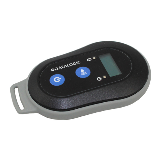
RFID Reader DLR-BT001 General Features The DLR-BT001-XX supports a Bluetooth® native key- board emulation allowing to interact directly with legacy application, office automation SW or any other generic solution requiring manual input. When paired to a smart- phone or to a tablet, the Device is a cost-effective alterna- tive to more expensive handheld devices. - Page 7 RFID Reader DLR-BT001 Figure 1. DLR-BT001-XX Front Panel Product Reference Guide...
-
Page 8: Front Panel Description
RFID Reader DLR-BT001 Front Panel Description The front panel is illustrated in Figure 1. on page 3and its five main features are described in the table below: Table 2- Front Panel LEDs and Buttons N° Name Description Display LCD Alphanumeric Display (8 chars x 2 lines). Indicates the Bluetooth®... -
Page 9: Acoustic And Vibration
RFID Reader DLR-BT001 Table 3- Reader Power LED Status Table Status Description Reader is active and the battery charge is in the Green range of 35÷100%. Reader is active and the battery charge is in the Orange range of 15÷35% Reader is active and the battery charge is in the range of 0÷15% Table 4- Reader Bluetooth LED Status Table... -
Page 10: Usb Connector
USB connector. Any attempt to access or replace the battery will cause an infringement of the warranty. In case of battery malfunction, please call Datalogic technical assistance. WARNING Accessories No. 1 B to A Type Micro USB No. -
Page 11: Disposal Of The Product
Battery Charger” with Code MBC-DLRBT001is available, too (to be ordered separately). See Fig- ure 3 below. For full details, refer to the MBC- NOTE DLRBT001 PRG, downloadable from the Datalogic Website. Figure 3. Multi Charger Unit or Docking Station Disposal of the Product Do not dispose the product in municipal or household waste. -
Page 12: Technical Specifications
RFID Reader DLR-BT001 Technical Specifications Item Description Physical Characteristics Reader Dimension 9.9 x 5.4 x 2.0 cm / 3.9 x 2.1 x 0.8 in Length of USB Cable 1.5 m / 4.9 ft Weight 57 g / 2.0 oz Electrical Characteristics Battery Battery Type: Li-Ion 3.7V, 570 mAh Operating: >12 hours with 40,000 tag read-... -
Page 13: Reader-Tag Link Profiles
RFID Reader DLR-BT001 Item Description User Environment Particulate and Water IP40 Sealing Operating 0° to 45°C / 32° to 113°F Temperature Storage Temperature -20° to 60°C / -4° to140°F Reader-Tag Link Profiles The DLR-BT001-XX readers support different modulations and return link profiles according to EPC Class1 Gen2 pro- tocol V.2.0. -
Page 14: Radiation Patterns
RFID Reader DLR-BT001 Radiation Patterns The radiation patterns of DLR_BT001-XX are shown in the following figures: Model – EU (ETSI) Figure 4. EU Radiation Pattern H Plane RFID Bluetooth® Pocket Reader DLRBT001... -
Page 15: Model - Us (Fcc)
RFID Reader DLR-BT001 Figure 5. EU Radiation Pattern V Plane Model – US (FCC) Figure 6. US Radiation Pattern H Plane Product Reference Guide... - Page 16 RFID Reader DLR-BT001 Figure 7. US Radiation Pattern V Plane RFID Bluetooth® Pocket Reader DLRBT001...
-
Page 17: Getting Started
Getting Started The reader can be connected to almost all devices sup- porting the Bluetooth® HID profile (keyboard emulation): tablets, smartphones, Windows-PC, Android devices, iOS, etc. To move the first steps and get familiar with the product you will need: •... -
Page 18: Introduction
Getting Started Figure 8. Temperature Logger Tag - DLR-TL001 Introduction The Product Reference Guide will help you to get started with your DLR-BT001-XX reader model. The Reader has two communication interfaces: Blue- tooth® and USB. Bluetooth® is the main interface and it uses the SPP profile (Serial Port Profile or HID), while the USB interface is mainly used for battery charging and firmware updating. -
Page 19: Using Dlr-Sw Profile
Getting Started host. When using BUFFER, please refer to chapter Using BUFFER Profile on page • This guide helps you to get started with your reader using the DLR-SW profile (over Bluetooth®, with SPP). The following table lists the allowed “Profiles – OpSys” choices for DLR-BT001-XX: Table 6- Compatibility between Profiles and primary OpSys <OS - PROFILE>... - Page 20 Getting Started Click on “Add Reader”; the next screen lists the allowed connection types: Click on “Bluetooth” in the “Connection Type” win- dow; the next screen asks for a confirmation: RFID Bluetooth® Pocket Reader DLRBT001...
- Page 21 Getting Started Click on “yes” to accept the Bluetooth permission request; the next screen displays the sensed device(s)/reader(s): Select your DLR-BT001 reader from the list of Blue- tooth® devices; the next screen asks for a passkey confirmation: Confirm the passkey. Once the connection is established, the Bluetooth®...
- Page 22 Getting Started To start using your DLR-BT001-XX, click on the reader line; the following screen invites you to start a search/inventory cycle of the tags being reach- able all around the reader. Click on “Start Inventory”; A list of sensed tags is shown, as in the example below: RFID Bluetooth®...
-
Page 23: Display Options In The Dlr-Sw Profile
So with this option you can customize the infor- mation displayed by the reader about the read tags (e.g., instead of the EPC you can display messages such as "correct tag"). Use the function PrintScreen (for more informa- tion, visit the Datalogic RFID SDK Software Product Reference Guide... - Page 24 Getting Started Development Kit web page and download the Datalogic RFID API Reference Manual) to cus- tomize the information displayed by the reader: C# representation: public void PrintScreen( string Text, string TerminalType Parameters: Name Description Text An arbitrary ASCII string.
-
Page 25: Reader-Host Communication Setup: Possible Cases
Getting Started The currently active CONTROL is marked with an asterisk. To activate a different CONTROL, scroll the CONTROL options by pressing quickly the trigger button until LOCAL or REMOTE is displayed. Hold down the trigger button for a few seconds: the name of the chosen option will begin to flash. - Page 26 Getting Started Case N° 1 BT – DLR-SW – ANDROID This is the first setup example given before. Case N° 2 BT – DLR-SW – WINDOW In this example a Win 8 OS is intended to be running on a Right click on the Bluetooth icon in the taskbar >...
- Page 27 Now you can use the DL RFID Software Controller Applica- tion to control the reader. The application could be down- loaded from the Datalogic website at the DLR-BT001-XX web page. Check the latest version of DL RFID Software Tool Controller for Windows software and install it. Refer to the manuals downloadable from the website to com- plete the needed steps.
- Page 28 Getting Started load VCP drivers for Windows based systems from the Datalogic RFID Website, in the SW/FW section. Open the System properties: go to “Control Panel “> “All Control Panel Items” > “System” and click on the option “Device Manager”.
- Page 29 Getting Started The activation of this version of DLR-SW profile is required to connect the DLR-BT001-XX in the case of Windows O.S. Follow the steps below to connect the reader using DLR- SW Controller for Windows via Bluetooth® (or via USB con- nection): Download from the DLR-BT001-XX web page the latest SW version of the DL RFID Software Tool Con-...
- Page 30 Getting Started Now the application is ready to accept a command / click on “Start Inventory” to display the information of the detected tags on the main window. For more information on the DL RFID Software Tool Con- troller for Windows application usage, please refer to the relevant user manual: you can download it from the DLR- BT001-XX webpage, Documents Section, or in the web area named Manuals and Documents.
- Page 31 Getting Started On the text editing App window you will see the EPCs of the tags: When configured in HID profile and paired to a device, the reader DLR-BT001-XX will automati- cally reconnect to the same device every time the Bluetooth®...
- Page 32 Getting Started When configured in HID profile and paired to a device, the DLR-BT001-XX will automatically reconnect to the same device every time the Blue- tooth® link is active (Reader switched ON and NOTE Bluetooth® activated on the host). This behavior can be verified looking at the blue LED.
-
Page 33: Options List In The Hid Profile
Getting Started As soon as the connection is established the Blue- tooth® blue LED turns on. Launch a Text Editing App (or any other App accept- ing a keyboard input). Start an inventory cycle by pressing the reader’s trigger button. On the text editing window you will find the EPCs of the detected tags: Options List in the HID Profile... -
Page 34: Display
Getting Started the chosen option will begin to flash. Once activated, the device returns to the main menu. DISPLAY Hold down the trigger button to enter the Display Option: SCROLL: Flowing text on display. To enable/disable the display scroll, hold down the trigger button for a few seconds. -
Page 35: Using Buffer Profile
Using BUFFER Profile The Buffer profile can be used when the communication links (USB or Bluetooth) are not available, for example in case of temporary missing of bluetooth communication. The operator can collects EPC codes, the reader store data into the internal buffer. When the BT link is up, or a USB cable is connected, the reader can send the buffered data if requested by the host. -
Page 36: Resetting The Dlr-Bt001-Xx Reader
Using BUFFER Profile Resetting the DLR-BT001-XX Reader Remind the Reader’s Front Panel at Figure 1. on page To reset the reader, press simultaneously power and trig- ger buttons for about six seconds, then release them. The reader will restart and restore to the “Default State”. Note that the reader SHALL NOT be connected to the USB port or to the battery charger during this reset action, otherwise... -
Page 37: Dlr-Bt001-Xx Configuration Of Main Menu & Aux Menu
DLR-BT001-XX Configuration of Main Menu & Aux Menu Introduction To access the MAIN MENU, turn on the device (power) and hold down the trigger button within two seconds. To scroll the main menu, press quickly the trigger button. The DLR_BT001’s configuration menu options are the fol- lowing: •... -
Page 38: Profile
DLR-BT001-XX Configuration of Main Menu & Aux Menu Figure 9. Reader’s Configuration Menu Structure PROFILE The PROFILE menu is the first option of the main menu. To select it, hold down the trigger button. Press the trigger button quickly to scroll the PROFILE options. -
Page 39: Beep
DLR-BT001-XX Configuration of Main Menu & Aux Menu • HID: choose this option to select the keyboard emula- tion protocol. For details on the use of the HID profile please refer to Options List in the HID Profile on page •... -
Page 40: Vibrate
DLR-BT001-XX Configuration of Main Menu & Aux Menu To enable / disable the submenu options, scroll the BEEP options menu by pressing quickly the trigger button until the desired BEEP option is displayed and then hold down trigger button for a few seconds. Scroll the enable and disable options by pressing quickly trigger button and hold down the... -
Page 41: Power
DLR-BT001-XX Configuration of Main Menu & Aux Menu POWER The POWER sub-menu allows to set the RF power level emitted by the reader. Note that, when the reader is configured under the DLR- SW profile, the power could also be set by using the DL RFID Software Tool Controller Application or the “Set- Power”... - Page 42 DLR-BT001-XX Configuration of Main Menu & Aux Menu The CLOCK menu is the last option of the menu. Hold down the trigger button to select it and enter its sub- menu. The CLOCK submenu options are the following: • Date: the date is the first option of the clock sub- menu.
-
Page 43: Firmware Upgrade
Firmware Upgrade The DLR-BT001-XX firmware upgrade can be managed via by using the SW Upgrade Program. The Upgrade Tool is available for free at the DLR-BT001- XX web page of the DL RFID Web Site, in the SW/FW sec- tion. To upgrade the firmware, follow the steps below: Connect the reader to the USB port of the PC. - Page 44 Firmware Upgrade In the window you will see the message “Found 1 device” (if the message is “No device connected” repeat the points 2, 3, 4 and 5). Select the FW image file to be used. Click on “Browse”. Click on “Upgrade Firmware” and wait for the upgrade process to be completed.
-
Page 45: Datalogic Limited Factory Warranty
Datalogic service center, with shipping charges prepaid. Datalogic shall pay for the return of the product to Customer if the shipment is to a location within the country in which the Da- talogic service center is located. - Page 46 No attempted assignment or transfer in violation of this provision shall be valid or binding upon Datalogic. DATALOGIC' S LIMITED WARRANTY IS IN LIEU OF ALL OTHER WARRANTIES, EXPRESS OR IMPLIED, ORAL OR WRITTEN, STATU- TORY OR OTHERWISE, INCLUDING, WITHOUT LIMITATION, ANY IMPLIED WARRANTIES OF MERCHANTABILITY, FITNESS FOR A PARTICULAR PURPOSE, OR NONINFRINGEMENT.
- Page 47 Risk of Loss Customer shall bear risk of loss or damage for product in transit to Datalogic. Datalogic shall assume risk of loss or damage for product in Datalogic’s possession. In the absence of specific writ- ten instructions for the return of product to Customer, Datalogic will select the carrier, but Datalogic shall not thereby assume any liability in connection with the return shipment.
-
Page 48: Services And Support
Firmware Upgrade Services and Support Datalogic provides several services as well as technical support through its website. Log on to www.datalogic. com and click on the links indicated for further informa- tion. Products Search through the links to arrive at your product page where you can download specific Manuals Service &... - Page 49 ©2017 Datalogic S.p.A. and/or its affiliates. All rights reserved. Datalogic and the Datalogic logo are registered trademarks of Datalogic S.p.A. in many countries, including the U.S.A. and the E.U. Datalogic S.r.l. Via San Vitalino 13 Calderara di Reno (BO) |40012...
Need help?
Do you have a question about the DLR-BT001 Series and is the answer not in the manual?
Questions and answers