Advertisement
Quick Links
B U L L E T I N
434
I N S T A L L A T I O N & O P E R A T I O N
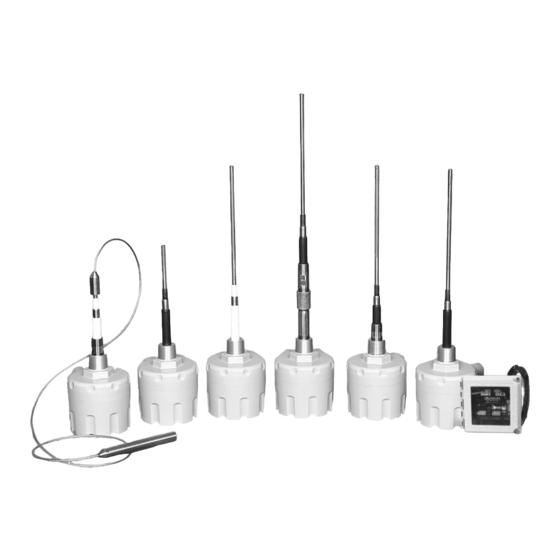
RF Capacitance Level Sensor
®
Model MK-2
True
ap
M o d e l M K - 2
Thank you for purchasing a quality product manufactured by Monitor
Technologies LLC. We realize that you do have a choice of vendors
when procuring RF Capacitance sensors and we sincerely appreciate
your business!
This manual contains the information necessary to ensure a safe and
successful installation. Please read and comply with the section on page
10 of this manual pertaining to SAFETY. Doing so will ensure proper
operation of the equipment and the safety of all personnel.
Before discarding shipping container, please inspect it thoroughly and
verify that all parts ordered are accounted for. Sometimes smaller parts
become stuck under carton flaps and other packaging materials.
In the event that information contained herein does not completely sat-
isfy your requirements or answer your questions, you may contact
Technical Support on our website www.monitortech.com, by e-mail at
techsupport@monitortech.com or by telephone at 1-800-766-6486
(1-630-365-9403). If your sensor ever requires service either in or out of
warranty, please contact us and obtain an RMA number prior to shipping
the unit to us.
®
www.monitortech.com
Advertisement

Related Manuals for Monitor TrueCap MK-2


Summary of Contents for Monitor TrueCap MK-2
- Page 1 True M o d e l M K - 2 Thank you for purchasing a quality product manufactured by Monitor Technologies LLC. We realize that you do have a choice of vendors when procuring RF Capacitance sensors and we sincerely appreciate...
- Page 2 P R E - I N S T A L L A T I O N C O N S I D E R A T I O N S Choosing a Location: (See Figure 2) 1) Material Flow - When selecting a location for the MK-2, choose a point in the vessel where the probe will be out of the direct flow of incoming and outgoing material to prevent any mechanical damage that may be caused by the pres-...
-
Page 3: Installation Recommendations
2) If using a welded coupling, cut a hole into the side/top of the vessel corresponding to the mounting connection (i.e. 1-1/2” BSPT, 1-1/4” NPT or 3/4” NPT). If using a Monitor mount- ing plate, cut a 2-1/2 inch (64 mm) center hole and six 11/32 inch (9 mm) mounting holes (for 5/16”... - Page 4 2) If using a welded coupling, cut a hole into the top of the vessel corresponding to O.D. of the 1-1/4” coupling used. If using a Monitor mounting plate, cut a 2-1/2 inch (64 mm) center hole and six 11/32 inch (9 mm) mounting holes (for 5/16” bolts) on a 7 inch (178 mm) bolt circle.
-
Page 5: Circuit Separation
Separation distances greater then the standard 12 feet marked appropriately as the disconnect for the associated (3.6m) or use of an interconnection cable other than Monitor's circuit. Assure the disconnect ratings are appropriately sized should not be attempted without the approval of Monitor's for the circuit protected (see Specifications). - Page 6 Test Function: C A L I B R A T I O N The MK-2 features a unique test feature that is initiated by the “TST” push-button. This feature allows users to test the oper- Calibration: ation and installation of the unit by effectively placing a capac- The calibration of the MK-2 is accomplished by the push-button itance value, via the electronics, directly on the probe.
- Page 7 Indicators: T R O U B L E S H O O T I N G 1) “CAL” green LED - Its status describes the “calibration” condition of the MK-2. Illumination indicates that the sensor PRObLEM: Sensor does not detect material. has successfully been calibrated.
- Page 8 M A I N T E N A N C E Fuse Replacement: The fuse incorporated into the MK-2 PCB is not intended for operator replacement. If necessary, consult the factory for additional technical assistance or for return of the MK-2. Preventive Maintenance: The MK-2 design is virtually maintenance free.
- Page 9 6 6 .91 6.91 M E C H A N I C A L S 175. 1 1 7 175.5 175.5 6 6 .50 6.50 DIMENSIONS ARE ShOwN IN INChES wITh MILLIMETER EquIVALENT IN bRACKETS 165. 1 1 6 165.0 165.0 4 4 .00 4.00...
- Page 10 True (industrial) (2) years from the date of purchase. The purchaser must notify Monitor of any defects within IEC 1000-4-11 Source voltage deviation the warranty period, return the product intact, and prepay transportation charges. The oblig- ation of Monitor Technologies LLC under this warranty is limited to repair or replacement at its factory.
Need help?
Do you have a question about the TrueCap MK-2 and is the answer not in the manual?
Questions and answers