Advertisement
Quick Links
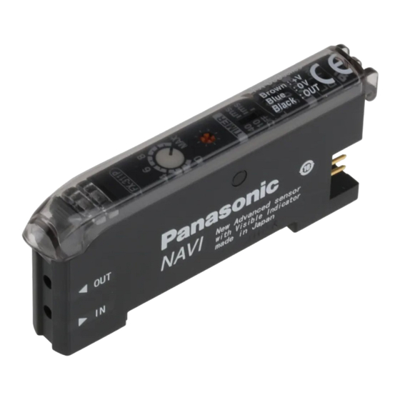
Manual Setting Fiber Sensor Amplifire
FX-311 Series
Thank you very much for purchasing Panasonic products. Please read this Instruction
Manual carefully and thoroughly for the correct and optimum use of this product.
Kindly keep this manual in a convenient place for quick reference.
Never use this product as a sensing device for personnel
●
protection.
In case of using sensing devices for personnel protection, use
●
products which meet standards, such as OSHA, ANSI or IEC
WARNING
etc., for personnel protection applicable in each region or
country.
1
SPECIFICATIONS
Type
Red LED type
NPN output
FX-311
Model
Item
PNP output
FX-311P
No.
Supply voltage
Power consumption
840mW or less (current consumption 35mA or less at 24V supply voltage)
<NPN output type>
NPN open-collector transistor
・Maximum sink current: 100mA (Note 1)
Output
・Applied voltage: 30V DC or less
(between output and 0V)
・Residual voltage: 1.5V or less
[at 100mA (Note 1) sink current]
Output operation
Short-circuit protection
Selectable: 250μs or
Response time
less (for S-D, STD),
2ms or less (for LONG)
Operation indicator
Orange LED (lights up when the output is ON)
Green LED (lights up under stable light-received condition or stable
Stability indicator
dark condition)
Sensitivity adjuster
12-turn potentiometer with indicator (Pointer part: red backlight) (Note 2)
Incorporated with OFF-delay timer, selectable either effective
Timer function
(approx. 10ms or 40ms) or ineffective
Interference prevention
Incorporated (up to four fibers can be mounted adjacently)
function
-10 to +55℃ (If 4 to 7 units are connected in cascade: -10 to +50℃,
Ambient temperature
if 8 to 16 units are connected in cascade: -10 to +45℃)
(No dew condensation or icing allowed), Storage: -20 to +70℃
Ambient humidity
Emitting element
Red LED (modulated)
Material
Enclosure: Heat-resistant ABS, Transparent cover: Polycarbonate
Weight
Notes: 1)
50mA if five, or more, amplifiers are connected together.
2)
The red backlight of the pointer part lights up when the power is turned ON and when the
sensitivity is adjusted.
3)
The cable for amplifier connection is not supplied as an accessory. Make sure to use the
optional quick-connection cables given below.
Main cable (3-core): CN-73-C1 (cable length 1m), CN-73-C2 (cable length 2m)
CN-73-C5 (cable length 5m)
Sub cable (1-core): CN-71-C1 (cable length 1m), CN-71-C2 (cable length 2m)
CN-71-C5 (cable length 5m)
2
CAUTIONS
This product has been developed / produced for industrial use only.
●
Make sure that the power supply is off while wiring.
●
Verify that the supply voltage variation is within the rating.
●
Take care that if a voltage exceeding the rated range is applied, or if an AC power
●
supply is directly connected, the sensor may get burnt or damaged.
In case noise generating equipment (switching regulator, inverter motor, etc.) is
●
used in the vicinity of this product, connect the frame ground (F.G.) terminal of the
equipment to an actual ground.
If power is supplied from a commercial switching regulator, ensure that the frame
●
ground (F.G.) terminal of the power supply is connected to an actual ground.
Do not use during the initial transient time (0.5 sec.) after the power supply is
●
switched on.
Take care that short-circuit of the load or wrong wiring may burn or damage the
●
sensor.
Do not run the wires together with high-voltage lines or power lines or put them in
●
the same raceway. This can cause malfunction due to induction.
Make sure to use the optional quick-connection cable for the connection of the
●
amplifier. Extension up to total 100m is possible with 0.3mm
However, in order to reduce noise, make the wiring as short as possible.
This sensor is suitable for indoor use only.
●
Avoid dust, dirt, and steam.
●
Take care that the sensor does not come in contact with water, oil, grease, organic
●
solvents, such as, thinner etc., or strong acid, and alkaline.
This sensor cannot be used in an environment containing inflammable or
●
explosive gases.
Never disassemble or modify the sensor.
●
Ramco National
INSTRUCTION MANUAL
Blue LED type
Green LED type
FX-311B
FX-311BP
FX-311GP
12 to 24V DC±10% Ripple P-P 10% or less
<PNP output type>
PNP open-collector transistor
・Maximum source current: 100mA (Note 1)
・Applied voltage: 30V DC or less
(between output and +V)
・Residual voltage: 1.5V or less
[at 100mA (Note 1) source current]
Selectable either Light-ON or Dark-ON
Incorporated
Selectable: 150μs or less (for FAST),
250μs or less (for STD), 2ms or less
(for LONG)
35 to 85% RH, Storage: 35 to 85% RH
Blue LED (modulated)
Green LED (modulated)
15g approx.
2
, or more, cable.
3
MOUNTING
How to mount the amplifier
Fit the rear part of the mounting section of the amplifier
①
on a 35mm width DIN rail.
Press down the rear part of the mounting section of the
②
unit on the 35mm width DIN rail and fit the front part of
the mounting section to the DIN rail.
How to remove the amplifier
Push the amplifier forward.
①
Lift up the front part of the amplifier to remove it.
②
Note:
Take care that if the front part is lifted without pushing the
amplifier forward, the hook on the rear portion of the mounting
section is likely to break.
How to connect the fiber cables
Be sure to fit the attachment to the fibers first before inserting the fibers to the
amplifier. For details, refer to the instruction manual enclosed with the fibers.
Snap the fiber lock lever down.
①
Insert the fiber cables slowly into the inlets until they
FX-311G
②
stop. (Note 1)
Return the fiber lock lever to the original position, till it
③
stops.
Notes: 1)
In case the fiber cables are not inserted to a position where
they stop, the sensing range reduces. In case of a flexible
fiber, take care that it may bend inside the amplifier, during
insertion.
2)
With the coaxial reflective type fiber, such as, FD-G4 or FD-FM2, insert the single-core fiber
cable into the beam-emitting inlet and the multi-core fiber cable into the beam-receiving
inlet. If they are inserted in reverse, the sensing accuracy will deteriorate.
4
CONNECTION
Make sure that the power supply is off while connecting or disconnecting the
quick-connection cable.
Connection method
Holding the connector of the quick-connection cable, align
①
its projection with the groove at the top portion of the
amplifier connector.
Insert the connector till a click is felt.
②
Disconnection method
① Pressing the projection at the top of the quick-connection
cable, pull out the connector.
Note:
Take care that if the connector is pulled out without pressing the
projection,
quick-connection cable whose projection has broken. Further, do
not pull by holding the cable, as this can cause a cable-break.
5
CASCADING AMPLIFIERS
Make sure that the power supply is off while adding or removing the amplifiers.
●
Make sure to check the allowable ambient temperature, as it depends on the
●
number of amplifiers connected in cascade.
In case two, or more, amplifiers are connected in cascade, make sure to mount
●
them on a DIN rail.
When the amplifiers move on the DIN rail depending on the attaching condition,
●
fitting them between the optional end plates (MS-DIN-E) mounted at the two ends.
When connecting in cascade, mount the amplifiers close to each other, fitting them
●
between the optional end plates (MS-DIN-E) mounted at the two ends.
Up to maximum 15 amplifiers can be added (total 16 amplifiers connected in cascade.)
●
When connecting more than two amplifiers in cascade, use the sub cable (CN-71-C□)
●
as the quick-connection cable for the second amplifier onwards.
The settings other than the interference prevention function cannot be transmitted
●
between this product and other digital fiber amplifiers. Therefore, in case both
models of amplifiers are mounted in cascade, be sure to mount identical models
together.
For mounting and removing the amplifier, refer to '
Cascading method
Mount the amplifiers, one by
①
one, on the 35mm width DIN
rail and make them close each
other.
Insert the connector of the
②
quick-connection cable to the
connector part of the amplifier.
Mount the optional end plates
③
(MS-DIN-E) at both the ends
to hold the amplifiers between
their flat sides.
Tighten the screws to fix the
④
end plates (MS-DIN-E).
Dismantling
Pressing the projection at the
①
top of the quick-connection
cable, pull out the connector.
Remove the amplifier.
②
www.PanasonicSensors.com
the
projection
may
break.
Do
not
Main cable (CN-73-C□)
(optional)
End plates (MS-DIN-E)
(optional)
②
①
35mm width DIN rail
①
②
③
①
Fiber
lock lever
②
Fiber
Groove
Projection
Quick-connection cable
Projection
use
a
MOUNTING'.
3
Sub cable (CN-71-C□)
(optional)
End plates (MS-DIN-E)
(optional)
1-800-280-6933
Advertisement

Related Manuals for Panasonic FX-311 Series


Summary of Contents for Panasonic FX-311 Series
-
Page 1: Specifications
① the mounting section to the DIN rail. 35mm width DIN rail Thank you very much for purchasing Panasonic products. Please read this Instruction How to remove the amplifier ① Manual carefully and thoroughly for the correct and optimum use of this product. - Page 2 Phone: +49-8024-648-0 to make 'assist function' effective, switch the operation selection switch in the order US Headquarter: Panasonic Electric Works Corporation of America L-ON (Light ON) → D-ON (Dark ON) → L-ON (Light ON). 629 Central Avenue New Providence, New Jersey 07974 USA Notes: 1) 'Assist function' cannot be used when adjusting sensitivity for moving objects.
Need help?
Do you have a question about the FX-311 Series and is the answer not in the manual?
Questions and answers