Table of Contents
Advertisement
Advertisement
Table of Contents

Subscribe to Our Youtube Channel
Related Manuals for Vaisala RS41-SG

Summary of Contents for Vaisala RS41-SG
- Page 1 M211667EN-G User Guide Vaisala Radiosonde RS41-SG and RS41-SGP...
- Page 2 Visit our Internet pages at www.vaisala.com. © Vaisala 2018 No part of this manual may be reproduced, contained in this manual. Vaisala makes no published or publicly displayed in any form or by representations on this manual’s compliance with any means, electronic or mechanical (including...
-
Page 3: Table Of Contents
About This Document..................5 Version Information.....................5 Related Manuals....................5 Documentation Conventions................6 Trademarks......................6 Regulatory Compliances..................6 Product Overview..................... 9 Introduction to Vaisala Radiosonde RS41............9 Unwinder......................10 Packing......................... 11 Product-Related Safety Precautions............... 12 ESD Protection....................12 Lithium Battery-Related Precautions.............. 13 Operation......................15 Preparing the Sounding..................15 Preparing the Radiosonde Balloon.............. - Page 4 RS41-SG and RS41-SGP User Guide M211667EN-G List of Figures Figure 1 Vaisala Radiosonde RS41 with Unwinder............10 Figure 2 RS41 Unwinder....................... 11 Figure 3 Radiosonde RS41 Optional Accessories............20 Figure 4 RS41 Unwinder Details..................23 Figure 5 Unwinder Clip Is Level with the Unwinder Bottom Plate......24 Figure 6 Ground Check Device RI41................26...
- Page 5 List of Tables List of Tables Table 1 Manual Versions....................... 5 Table 2 Related Manuals....................... 5 Table 3 Unwinder Properties..................... 10 Table 4 RS41 LED Lights.....................30...
- Page 6 RS41-SG and RS41-SGP User Guide M211667EN-G...
-
Page 7: About This Document
SGP, referred to as RS41 in this manual. For information on the sounding software, see the appropriate sounding system documentation. In this manual, RS41 refers to Radiosonde RS41-SG and RS41-SGP, unless otherwise mentioned. RI41 refers to both RI41 and RI41-B, unless otherwise mentioned. -
Page 8: Documentation Conventions
Indicates that you need to take some notes during the task. 1.4 Trademarks DigiCORAâ and MARWINâ are registered trademarks of Vaisala Oyj. 1.5 Regulatory Compliances Vaisala Radiosonde RS41 complies with the following performance and environmental test standards: • 2004/108/EC Electromagnetic Compliance: EN 61000-4-2, EN 61000-4-3 and EN 55022 / EN 302 054-2 •... - Page 9 Chapter 1 – About This Document • RoHS compliance: RoHS Directive (2011/65/EC)
- Page 10 RS41-SG and RS41-SGP User Guide M211667EN-G...
-
Page 11: Product Overview
Vaisala Radiosonde RS41 temperature sensor utilizes linear resistive platinum technology. The small size of the sensor results in low solar radiation error and guarantees fast response. Wind data, height and pressure are derived from Vaisala Radiosonde RS41 GPS data combined with differential corrected GPS data from the ground station. -
Page 12: Unwinder
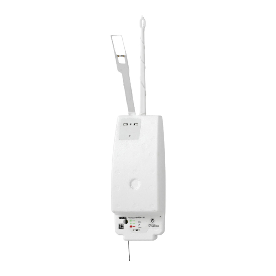
RS41-SG and RS41-SGP User Guide M211667EN-G Figure 1 Vaisala Radiosonde RS41 with Unwinder Sensor boom Power switch Additional sensor interface connector Antenna LED light Unwinder Unwinder stick 2.2 Unwinder The unwinder is specifically designed for use with Radiosonde RS41. The unwinder is installed to the radiosonde so that it bends the sensor boom to the correct sounding position, ensuring repeatable results in the soundings. -
Page 13: Packing
Chapter 2 – Product Overview Object Property Length of the string 55 m Unwinder weight with stick 29 g The unwinders are shipped in the radiosonde package, packed separately from the radiosondes. This allows the operator to prepare the balloon and the unwinder at a time that is most convenient. -
Page 14: Product-Related Safety Precautions
Do not use the radiosonde without consultation and cooperation with local and other applicable aviation authorities. WARNING! Vaisala recommends the use of a parachute even if it is not required by applicable restrictions. CAUTION! Do not modify the unit. Improper modification can damage the product or lead to malfunction. -
Page 15: Lithium Battery-Related Precautions
Chapter 2 – Product Overview • If you are unable to take either precaution, touch a conductive part of the equipment chassis with your other hand before touching ESD-sensitive components. • Hold component boards by the edges and avoid touching component contacts. 2.6 Lithium Battery-Related Precautions CAUTION! Take the following precautions when handling lithium batteries:... - Page 16 RS41-SG and RS41-SGP User Guide M211667EN-G...
-
Page 17: Operation
Chapter 3 – Operation 3. Operation 3.1 Preparing the Sounding You must carry out the pre-launch steps as instructed and always in the same way. The workorder for a sounding is listed below. See the following sections for details. 1. Unpack and fill the balloon. Prepare the optional sounding accessories. 2. -
Page 18: Filling The Balloon
(or hydrogen generator) with a flexible plastic hose. 2. Select the nozzle which best fits into the neck of the balloon. 3. Load the additional weights that are needed to obtain the required lift, for example, Vaisala Filling Balance FB13 weights as in the figure below. - Page 19 Chapter 3 – Operation 4. Secure the neck of the balloon to the balance nozzle with a clamp as shown in the figure below. Look out for sharp objects near the filling balance so that no damage is caused to the relaxed balloon. 5.
- Page 20 RS41-SG and RS41-SGP User Guide M211667EN-G 6. When the balloon is sufficiently filled, in other words, the balloon just raises the gas nozzle, close the gas valve. 7. Before removing the balloon from the gas nozzle, tie the neck of the balloon tightly...
- Page 21 Chapter 3 – Operation 8. Remove the balloon from the gas nozzle. 9. Fold the neck of the balloon over and secure firmly. Cut off any extra string. The figure below shows an example of a secured balloon neck. In the figure, the balloon is attached to a balloon holder hook.
-
Page 22: Preparing Optional Sounding Accessories
RS41-SG and RS41-SGP User Guide M211667EN-G 3.3 Preparing Optional Sounding Accessories The unwinder is designed to be attached directly to the folded balloon neck, but in case you cannot attach the unwinder to the balloon, the unwinder can also be used with optional sounding accessories which provide the necessary support during the sounding. -
Page 23: Totex Parachute 5710-5
3.3.1 Totex Parachute 5710-5 The recommended parachute is Totex type 5710-5 (Vaisala code 15045). See option 1 in Figure 3 (page 20). Totex parachute 5710-5 has an elastic ribbon loop below the spreader. Attach the unwinder to the loop by pushing the hook out the other side in the same fashion as with the folded balloon neck. -
Page 24: Preparing Rs41 Unwinder
RS41-SG and RS41-SGP User Guide M211667EN-G 3. Tie a string on the unwinder hook. 4. Thread the string through the four holes so that the unwinder is firmly attached to the other end of the hanger board. 5. Pull the same string through the hole at the other end of the hanger board and attach the string to the parachute. -
Page 25: Handling The Unwinder String
Chapter 3 – Operation 2. When you pull the unwinder stick out, make sure that the string unwinds and that it is not tangled. Figure 4 RS41 Unwinder Details Unwinder stick Unwinder hook Unwinder bottom plate Unwinder clip 3.4.2 Handling the Unwinder String In the unwinder body, the unwinder string runs under a round plastic clip (number 4 in Figure 4 (page 23)) on the bottom plate. -
Page 26: Attaching The Unwinder To The Balloon
RS41-SG and RS41-SGP User Guide M211667EN-G 2. If the clip is bent up, bend it gently back to level position as shown in Figure 5 (page 24). Figure 5 Unwinder Clip Is Level with the Unwinder Bottom Plate 3.4.3 Attaching the Unwinder to the Balloon... -
Page 27: Preparing The Radiosonde With Ground Check Device Ri41
Chapter 3 – Operation 3. Align the unwinder so that it points directly downwards from the balloon neck, as illustrated in the figure below. CAUTION! To ensure a successful sounding, align the unwinder so that it points downwards from the balloon neck. 3.5 Preparing the Radiosonde with Ground Check Device RI41 In the sounding preparations, RI41 is connected to the sounding software computer via a... -
Page 28: Figure 6 Ground Check Device Ri41
RS41-SG and RS41-SGP User Guide M211667EN-G Figure 6 Ground Check Device RI41 CAUTION! Do not touch the radiosonde sensors, they are fragile and can be easily contaminated. During radiosonde regeneration, the temperature of the sensor boom is about 150 °C for... - Page 29 Chapter 3 – Operation Follow the steps below to prepare the radiosonde for a sounding with RI41: 1. Open the radiosonde package and remove the radiosonde from the package. The foil bag contains illustrated instructions for preparing the radiosonde. 2. Place the radiosonde on RI41 carefully. The radiosonde is automatically switched on when placed on RI41.
- Page 30 RS41-SG and RS41-SGP User Guide M211667EN-G 4. During the radiosonde pre-flight preparation phase, several steps are carried out. These consist of ground check procedures for sensors, as well as optional features for setting the radiosonde in-flight operation parameters, such as a timer for turning the radiosonde power off after a desired time, pressure, or altitude.
-
Page 31: Preparing Rs41 Sensor Boom
Chapter 3 – Operation 3.6 Preparing RS41 Sensor Boom Before launching the radiosonde, bend the sensor boom to the correct sounding position using the unwinder stick. This also attaches the radiosonde to the unwinder and the balloon. 1. Push the unwinder stick to its position at the end of the radiosonde. 2. -
Page 32: Checking The Led Light
RS41-SG and RS41-SGP User Guide M211667EN-G 3. Make sure that the unwinder is firmly attached to the radiosonde. 3.7 Checking the LED Light After preparing the radiosonde for the sounding, check the radiosonde status by checking the LED light on the radiosonde cover. When the green LED light is steady, the radiosonde is ready for the release. -
Page 33: Storage And Transportation
4.2 Transportation Vaisala radiosondes must be transported in their original shipping packages.These packages are designed and built to survive and protect their contents in the environmental conditions described herein with the terminology and standards per standard IEC 60721-3-2. The... -
Page 34: Figure 7 Lithium Battery Handling Label
RS41-SG and RS41-SGP User Guide M211667EN-G • The consignment must include a document indicating the lithium content, describing proper handling and procedures for damaged packages, and a telephone number for additional information. Figure 7 Lithium Battery Handling Label If the lithium battery is faulty, do not transport it. -
Page 35: Appendix A: Safety Instructions For Balloon Operators
Appendix A – Safety Instructions for Balloon Operators Appendix A. Safety Instructions for Balloon Operators Photocopy these instructions and place the list in clear view in the balloon filling shed and in the sounding compartment. WARNING! New operator! Carefully study the instructions for using the hydrogen generator and for the correct method of inflation. - Page 36 RS41-SG and RS41-SGP User Guide M211667EN-G 14. Always keep the radiosonde at least 50 cm below the level of the gas nozzle and the inflated balloon, and at least 1.5 meters away from the gas cylinder/hydrogen generator, connectors, and tubing. Avoid taking the radiosonde inside the balloon filling shed, if possible.
-
Page 37: Appendix B: Radiosonde Warranty
Appendix B – Radiosonde Warranty Appendix B. Radiosonde Warranty... - Page 38 RS41-SG and RS41-SGP User Guide M211667EN-G...
-
Page 39: Technical Support
Technical Support Contact Vaisala technical support at helpdesk@vaisala.com. Provide at least the following supporting information: • Product name, model, and serial number • Name and location of the installation site • Name and contact information of a technical person who can provide further information on the problem For more information, see www.vaisala.com/support. - Page 40 RS41-SG and RS41-SGP User Guide M211667EN-G...
- Page 42 www.vaisala.com...
Need help?
Do you have a question about the RS41-SG and is the answer not in the manual?
Questions and answers