
Subscribe to Our Youtube Channel
Related Manuals for Raychem C910-485


Summary of Contents for Raychem C910-485
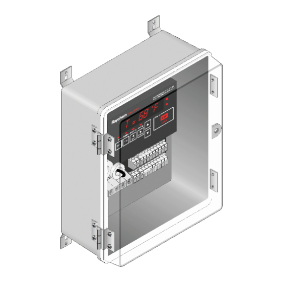
- Page 1 C910-485 Heat Trace Controller INSTALLATION, OPERATION AND MAINTENANCE MANUAL Firmware versions up to V4.0X nVent.com | 1...
-
Page 2: Table Of Contents
Section 3 Operator Console ......................14 3.1 Alphanumeric Display ......................14 3.2 Keypad ..........................14 3.3 LED Indicators ........................15 Section 4 C910-485 Operation ...................... 16 4.1 Operating Modes ........................ 16 4.1.1 Four Modes of Console.................... 16 4.2 Console Mode Menus ......................18 4.2.1 Alphanumeric Tag Assignment ................ -
Page 3: Section 1 Overview
This document covers the C910-485 Heat Trace Controller and its available options. To ensure that you are using the correct documentation for your particular version of controller, please check the firmware version number of your C910-485 against the version number listed on the front of this manual. - Page 4 Buyer. However, the Buyer shall pay all shipping charges, duties, and taxes for products returned to nVent from another country. nVent warrants that the software and firmware designated by nVent for use with the C910-485 Controller will execute its programming instructions properly. nVent does not warrant that the operation of the hardware, or software, or firmware will be uninterrupted or error-free.
-
Page 5: Product Specification
Exclusive Remedies The remedies provided herein are the buyer’s sole and exclusive remedies. nVent shall not be liable for any direct, indirect, special, incidental, or consequential damages, whether based on contract, tort, or any other legal theory. Conducted and Radiated Emissions—FCC/DOC Statement of Compliance This equipment has been tested and found to comply with the limits for a Class A digital device, pursuant to Part 15 of the FCC rules. - Page 6 Monitoring Temperature Low alarm range 0°F to 180°F (–18°C to 82°C) or OFF High alarm range 0°F to 200°F (–18°C to 93°C) or OFF Ground fault Alarm range 20 mA to 100 mA Trip range 20 mA to 100 mA Current Low alarm range 0.3 A to 30 A or OFF Autocycle...
- Page 7 Programming and Setting Method Programmable keypad, or ACS-30 user interface network Units Imperial (°F, in.) or Metric (°C, mm) Digital display Actual temperature, control temperature, heating cable current, ground fault, programming parameter values, alarm values LEDs Current mode, heating cable on, alarm condition, receive/transmit data Memory Nonvolatile, restored after power loss, checksum data...
-
Page 8: Section 2 Installation And Wiring
INSTALLATION AND WIRING 2.1 INTRODUCTION This section includes information regarding the initial inspection, preparation for use, and storage instructions for the C910-485 Heat Trace controllers. 2.2 INITIAL INSPECTION Inspect the shipping container for damage. If the shipping container or cushioning material is damaged, it should be kept until the contents of the shipment have been verified and the equipment has been checked mechanically and electrically. -
Page 9: Wiring
Figure 2.2 – Power Connection 2.5.1 Power Connections The C910-485 controller may be powered directly from a 100 V to 277 V supply. All of the power terminals are labeled for easy identification. Do not attempt to use wire sizes that exceed the marked terminal ratings and avoid terminating two wires on the same terminal whenever possible. -
Page 10: Temperature Sensor And Extension Cables
2.5.2 Temperature Sensor and Extension Cables The C910-485 has two (2) RTD inputs. Use only 3-wire 100 Ω Platinum RTDs (DIN 43760, α= 0.00385 Ω/ Ω/°C) Note: The RAYCHEM C910-485 default is set for one RTD in position one. If a second RTD is installed in position two, the controller must be power cycled to recognize the RTD. - Page 11 Alarm Output Wiring Figure 2.6 – Used As a Dry Contact Figure 2.7 – Used As a Switched DC Contact Figure 2.8 – Used As an AC Alarm Relay nVent.com | 11...
-
Page 12: Communication Signal Connections
Figure 2.11 – Used as a Powered AC Alarm Relay 2.6.1 Communication Signal Connections The C910-485 controller includes a RS-485 communications interface. Use twisted pair, shielded cable communication wiring. Ground the shield on communications wiring at one end only, using the terminals provided. -
Page 13: Initializing The Controller
Figure 2.12 – Communication Wiring (C910-485 only) RS-485 (2-Wire) Connections 2.7 INITIALIZING THE CONTROLLER 2.7.1 Initial Heating Cable Test To minimize the risk of damage to the controller due to a heating cable fault, the integrity of the heating cable should be verified by performing the commissioning tests detailed in the appropriate product installation and operating manual. -
Page 14: Section 3 Operator Console
Section 3 OPERATOR CONSOLE 3.1 ALPHANUMERIC DISPLAY The console incorporates a six characters, fourteen segment, plus decimal LED display. Messages and prompts that are greater than six characters long are scrolled, allowing more meaningful, non-cryptic messages to be used. 3.2 KEYPAD The local keypad consists of six keys that allow you to select the console mode function that you are interested in. -
Page 15: Led Indicators
Two additional LEDs are used to indicate external communications activity and are only used with the C910-485 with the optional RS-485 communications interface. The “Rx” LED flashes to show that the Controller is receiving information via its communications port. -
Page 16: Section 4 C910-485 Operation
Section 4 C910-485 OPERATION 4.1 OPERATING MODES 4.1.1 Four Modes on Console Scan This is the default mode displayed during normal operation. In this mode, the console sequentially displays load current, temperature, and setpoint readings. Alarm This mode allows you to examine or reset any alarms that may exist. The LED above the ALARM key is illuminated while in this mode. - Page 17 nVent.com | 17...
-
Page 18: Console Mode Menus
4.2 CONSOLE MODE MENUS The Console Mode Menu Index below shows all user interface parameters. This menu shows the Factory Default along with the associated range. The section column refers to the section in this manual that illustrates the actual keystrokes required to input the parameters. -
Page 19: Alphanumeric Tag Assignment
4.2.1 Alphanumeric Tag Assignment Purpose A 19 character alphanumeric TAG may be assigned to a control point to allow it to be easily associated with a pipe, vessel, process, circuit, drawing name, or number. Setting Any combination of 19 characters from A–Z, 0–9, /, -, ., (, ), or #. nVent.com | 19... -
Page 20: Setting Units
4.2.2 Setting Units This allows selection of the type units (temperature or size) to display on Purpose the operator. Metric or Imperial Imperial Setting Factory Default nVent.com | 20... -
Page 21: Switch Control Mode
4.2.3 Switch Control Mode Purpose This allows selection of the type of algorithm to be used to maintain the control setpoint temperature. Reference Figure 2.5 for the External Direct wiring schematic.) Setting On/Off or Proportional Ambient Factory Default On/off Sensing Control (PASC), External Direct nVent.com | 21... -
Page 22: Control Setpoint
4.2.4 Control Setpoint Purpose This is the temperature that the controller uses to determine whether its output switch should be on or off. Setting/Range 0°F to 200°F (–18°C to 93°C) Factory Default 40°F (4°C) nVent.com | 22... -
Page 23: Deadband
4.2.5 Deadband Purpose The deadband is a window of difference between the measured control temperature and the desired control setpoint temperature and provides the decision to turn the output off or on Setting/Range 1°F to 10°F (1°C to 6°C) Factory Default 5°F (3°C) nVent.com | 23... -
Page 24: Proportional Ambient Sensing Control (Pasc)
4.2.6 Proportional Ambient Sensing Control (PASC) Purpose This control mode sets Proportional Ambient Sensing Control (PASC). See Appendix A for more details. Setting Range Factory Default Pipe Size (inch): ½, 1 or, ≥ 2 ½- Control Setpoint: 0 to 200°F (–18 to 92°C) 40°F (4°C) Min. -
Page 25: Low Temperature Alarm: Enable (Lo Ts 1 And Lo Ts 2)
4.2.7 Low Temperature Alarm: Enable (Lo TS 1 and Lo TS 2) Purpose This allows the user to enable or disable the low temperature alarm for temperature sensor number 1 and 2. Alarm time delay filter is factory set at 15 minutes. Setting/Range Enable or disable Factory Default... -
Page 26: Low Temperature Alarm: Setting (Lo Ts 1 And Lo Ts 2)
4.2.8 Low Temperature Alarm: Setting (Lo TS 1 and Lo TS 2) Purpose This allows the user to set the low temperature alarm setting for temperature sensor number 1 and 2. Alarm time delay filter is factory set at 15 minutes. Setting/Range 0°F to 180°F (–18 to 82°C) Factory Default... -
Page 27: High Temperature Alarm: Enable (Hi Ts 1 And Hi Ts 2)
4.2.9 High Temperature Alarm: Enable (Hi TS 1 and Hi TS 2) Purpose This allows the user to enable or disable the high temperature alarm for temperature sensor number 1 and 2. When enabled, high limit cutout feature will force the controller output off if the temperature reading exceeds the HIGH ALARM temperature setting. -
Page 28: High Temperature Alarm: Setting (Hi Ts 1 And Hi Ts 2)
4.2.10 High Temperature Alarm: Setting (Hi TS 1 and Hi TS 2) Purpose This allows the user to set the high temperature alarm Setting for temperature sensor number 1 and 2. Alarm time delay filter is factory set at 15 minutes. Setting/Range 0°F to 200°F (–18°... -
Page 29: Temperature Sensor Failure Alarm
4.2.11 Temperature Sensor Failure Alarm Purpose This allows the user to enable or disable the temperature sensor failure alarm. Alarm time delay filter is factory set < 2 minutes. Setting/Range Enable or disable Factory Default Disable nVent.com | 29... -
Page 30: High Temperature Cut-Out, Setpoint And Alarm (Hi Limit Ts1/Hi Limitts2)
4.2.12 High Temperature Cut-out, Setpoint and Alarm (HI Limit TS1/HI limitTS2) Purpose Set high temperature alarm and cut-out values. Settings/Ranges: Factory Defaults: Enable/Disable HI Limit Disable Set point: 0°F (-18°C) to 200°F (93°C) 200°F (93°C) Enable/Disable Alarm Disable nVent.com | 30... -
Page 31: Low Load Current Alarm: Enable (Lo Load)
4.2.13 Low Load Current Alarm: Enable (Lo Load) Purpose This allows the user to enable or disable the low load current alarm to detect current levels which are lower than a preset limit for the application. Alarm time delay filter is factory set at < 2 minutes. Setting/Range Enable or disable Factory Default... -
Page 32: Low Load Current Alarm: Setting (Lo Load)
4.2.14 Low Load Current Alarm: Setting (Lo Load) Purpose This allows the user to set the low load current alarm level. Alarm time delay filter is factory set at < 2 minutes. Setting/Range 0.3 A to 30 A or off Factory Default nVent.com | 32... -
Page 33: Factory Default Settings (Load Defaults)
4.2.15 Factory Default Settings (Load Defaults) Purpose To provide a quick method of re-Setting the controller’s configuration parameters to the Factory Default parameters. Setting Factory Default nVent.com | 33... -
Page 34: Ground-Fault Current Alarm Level (Hi Gf Alarm)
4.2.16 Ground-fault Current Alarm level (Hi GF Alarm) Purpose This allows the user to set the ground-fault current alarm level. Exceeding this limit will trigger the alarm to indicate that a ground- fault condition exists in the heating cable circuit. To protect against the risk of fire or shock, ground-fault level should be set at the lowest level possible to allow normal operation of the cable. -
Page 35: Ground-Fault Current Trip Level (Hi Gf Trip)
4.2.17 Ground-fault Current Trip Level (Hi GF Trip) Purpose This allows the user to set the ground-fault current trip level. Exceeding this limit will result in the output switch being latched off and the Ground-fault Level Trip Alarm activated to indicate a ground fault condition. -
Page 36: Temperature Sensor Failure Mode
4.2.18 Temperature Sensor Failure Mode Purpose This mode sets the controller to turn the output switch ON or OFF if all selected temperature sensors fail. Setting/Range On or off Factory Default nVent.com | 36... -
Page 37: Temperature Sensor Control Mode (Ts Clt Mode)
4.2.19 Temperature Sensor Control Mode (TS CLT Mode) Purpose The TS CONTROL MODE allows the selection of one of eight possible temperature control modes for the controller. The different modes allow redundant fail-safe temperature sensing. 1. TS1-Fail ON Setting/Range 5. Average Fail ON 2. -
Page 38: External Input: Inhibit Or Force On
4.2.20 External Input: Inhibit or Force on. Purpose Using an external input device to override sensor inputs: Force on or force off. Reference Figure 2.5 for the wiring connection schematic. Setting/Range Factory Default Ext Input: Not used, Force on or Inhibit Not used Override: Remote or External input Remote... -
Page 39: Firmware Version
4.2.21 Firmware Version Purpose This menu displays the revision level of the firmware programmed into the controller. Setting/Range Factory Default nVent.com | 39... -
Page 40: Passcode
4.2.22 Passcode Purpose The four digit numeric PASSWORD stops unauthorized users from modifying the controller’s configuration parameters using the Operator Console. Setting/Range 0000 to 9999 Factory Default 0000 nVent.com | 40... -
Page 41: Communications Setup
4.2.23 Communications Setup Purpose Defines the communications language used by the controller to communicate with other devices. The C910-485 only communicates using Modbus Protocol. The C910-485 automatically detects when it is connected to the ACS-30 network. Setting/Range See C910-485 Factory Default... - Page 42 Modbus RTU MODBUS protocol. Modbus ASCII For a detailed description of the controller’s MODBUS mapping please refer to C910-485 Heat Trace Controller. Note: HTCBus is for factory use only. Modbus Addr 1 - 247 Set the communications address as desired.
-
Page 43: Auto-Cycle: Enabling
4.2.24 Auto-Cycle: Enabling Purpose The autocycle function applies power to the heating cable circuit for approximate 10 seconds at the selected interval. It is used to test the integrity of the heating cable circuit. Note: Although the autocycle function helps monitor the functionality of the heating cable circuits it does not eliminate the need for preventive maintenance as detailed in the heating cable operating manuals. -
Page 44: Auto-Cycle: Interval
4.2.25 Auto-Cycle: Interval Purpose Set the interval for running the autocycle procedure Setting/Range 1 to 240 [minutes or hours, selected Factory Default in the Auto-cycle units menu.] nVent.com | 44... -
Page 45: Auto-Cycle: Units
4.2.26 Auto-Cycle: Units Purpose Select the Autocycle interval time units. Setting/Range Minutes or hours Factory Default Hours nVent.com | 45... -
Page 46: Contactor Count
4.2.27 Contactor Count Purpose Generates an alarm if the number of off-to-on transitions of a contactor reaches or exceeds the Contactor Count Alarm Setting. This serves as a method to perform preventative maintenance on the contactor before a failure is likely to occur. Setting/Range 0 to 999,999 Factory Default... -
Page 47: Monitor And Maintenance Menus
4.2.28 Monitor and Maintenance Menus Purpose The Monitor menu displays the measured and stored readings. You can also reset counters from this menu. Setting/Range See C910-485 Monitoring Factory Default and Maintenance Parameters table. nVent.com | 47... - Page 48 Operator Console to ensure that they are functioning properly. Recorded Values Temperature values This feature indicates the maximum and minimum temperatures recorded by the C910-485 since the last time the values were reset: Max Control temp Min Control temp TS 1 Max Temp...
-
Page 49: Acknowledging And Resetting Alarms
4.2.29 Acknowledging and Resetting Alarms Purpose To acknowledge and reset any alarm conditions that may exist. Use the Up / Down Arrow keys to examine the next/previous active alarms. Setting/Range See Alarm Filter Times Factory Default Alarm Filter Times Alarm Type Filter Time Lo TS 1 and 2 15 minutes... -
Page 50: Alarm Output Normal State
4.2.30 Alarm Output Normal State Purpose Configures both the alarm output relays (dry contact and AC alarm) for normally open or normally closed operation. The normal condition is assumed to be when the HTC is powered and no alarms exist. Setting/Range Normally Open (N.O.) or Factory Default... -
Page 51: Section 5 Troubleshooting
Section 5 TROUBLESHOOTING The C910-485 may be used as an effective troubleshooting tool to pinpoint problem areas of heating cable circuits. Described below are a few of the more common problem areas, their symptoms, and parameters to check to determine the actual faulty portion of the heating cable circuit. - Page 52 Ground-fault Incorrect installation, Perform heating cable commissioning alarms wet system tests outlined in the heat cable operation components or manuals. damaged cables. Incorrect neutral return Check that the heating cable circuit wiring neutrals return to the controller and are not connected directly to the distribution panel.
-
Page 53: Section 6 Appendix A: Proportional Ambient Sensing Control (Pasc)
The C910-485 has a control algorithm that uses the measured ambient temperature, desired maintain temperature, minimum ambient temperature assumption used during design, and size of the smallest pipe diameter to calculate how long the heating cable should be on or off to maintain a near-constant pipe temperature. - Page 54 ©2018 nVent. All nVent marks and logos are owned or licensed by nVent Services GmbH or its affiliates. All other trademarks are the property of their respective owners. nVent reserves the right to change specifications without notice. Raychem-IM-H58415-C910series-EN-1805 nVent.com | 54...
Need help?
Do you have a question about the C910-485 and is the answer not in the manual?
Questions and answers