Table of Contents
Advertisement
Quick Links
D-E451/E455/E456CK/E459CK
SERVICE MANUAL
Ver 1.0 1999.06
CD player
System
Compact disc digital audio system
Laser diode properties
Material: GaAIAs
Wavelength : λ= 780 nm
Emission duration: Continuous
Laser output : Less than 44.6 µW (This output
is the value measured at a distance of 200 mm
from the objective lens surface on the optical
pick-up block with 7 mm aperture. )
Error correction
Sony Super Strategy Cross Interleave Reed
Solomon Code
D-A conversion
1-bit quartz time-axis control
Frequency response
+1
20 - 20,000 Hz
dB (measured by EIAJ CP-
-2
307)
Output (at 4.5 V input level)
Headphones (stereo minijack)
15 mW + 15 mW at 16 ohms
Line output (stereo minijack)
Output level 0.7 V rms at 47 kilohms
Recommended load impedance over 10
kilohms
MICROFILM
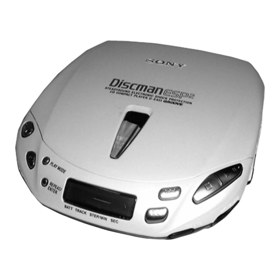
Photo : D-E451
Model Name Using Similar Mechanism
CD Mechanism Type
Optical Pick-up Type
SPECIFICATIONS
General
Power requirements
For the area code of the model you purchased,
check the upper left side of the bar code on the
package.
• Sony BP-DM10 Rechargeable battery:
2.4 V DC, Ni-Cd, 650 mAh
Sony BP-DM20 Rechargeable battery:
2.4 V DC, Ni-MH, 1,200 mAh
• Two LR6 (size AA) batteries: 3 V DC
• AC power adaptor (DC IN 4.5 V jack):
US model: 120 V, 60 Hz
• Sony DCC-E245 car battery cord for use on
car battery : 4.5V DC
Dimensions (w/h/d) (without projecting parts and
controls)
Approx. 129 x 28 x 146 mm
( 5
1
/
x 1
1
/
x 5
3
/
in.)
8
8
4
Mass (without rechargeable battery)
Approx. 220 g (7.8 oz)
Operating temperature
5°C - 35°C (41°F - 95°F)
COMPACT DISC COMPACT PLAYER
US Model
D-E441
CDM-2811EAA
DAX-11E
Supplied accessories
For the area code of the model you purchased,
check the upper left side of the bar code on the
package.
D-E451
AC power adaptor (1)
Headphones (1)
D-E455
AC power adaptor (1)
Headphones with remote control (1)
Rechargeable battery (1)
D-E456CK
AC power adaptor (1)
Headphones (1)
Car battery cord (1)
Car connecting pack (1)
Velcro tape (2)
Spare fuse (1)
Spiral tube (1)
D-E459CK
AC power adaptor (1)
Rechargeable battery (1)
Headphones with remote control (1)
Car battery cord (1)
Car connecting pack (1)
Velcro tape (2)
Spare fuse (1)
Spiral tube (1)
Design and specifications are subject to
change without notice.
Advertisement
Table of Contents

Related Manuals for Sony D-E451


Summary of Contents for Sony D-E451
- Page 1 Rechargeable battery (1) Error correction US model: 120 V, 60 Hz D-E456CK Sony Super Strategy Cross Interleave Reed • Sony DCC-E245 car battery cord for use on AC power adaptor (1) Solomon Code car battery : 4.5V DC Headphones (1)
-
Page 2: Table Of Contents
MARK ! ON THE SCHEMATIC DIAGRAMS AND IN THE PARTS LIST ARE CRITICAL TO SAFE OPERATION. CAUTION REPLACE THESE COMPONENTS WITH SONY PARTS WHOSE Use of controls or adjustments or performance of procedures other than PART NUMBERS APPEAR AS SHOWN IN THIS MANUAL OR IN those specified herein may result in hazardous radiation exposure. -
Page 3: Servicing Notes
SECTION 1 SERVICING NOTES 5. Calculate the current value by the reading of the digital voltmeter. NOTES ON HANDLING THE OPTICAL PICK-UP BLOCK OR Reading of the tester (V) ÷ 4.7 ( Ω ) = current value (A) BASE UNIT (Example) Reading of the digital voltmeter of 0.2256 V : 0.2256 V ÷... -
Page 4: General
SECTION 2 GENERAL LOCATION AND FUNCTION OF CONTROLS 1 234 !¶ !§ !∞ !¢ !£ !™ !¡ ESP (Electronic Shock Protection) button 2 /REMOTE jack ! ¡ OPEN button AVLS switch !™ DC IN 4.5V jack ∑ VOLUME control ! £ PLAY MODE button SOUND button ! ¢... -
Page 5: Disassembly
SECTION 3 DISASSEMBLY The equipment can be removed using the following procedure. Lid ASSY, Upper Cabinet (Upper) ASSY, Cabinet (Lower) sub ASSY, MD ASSY Main board, LED sub board (E456CK, E459CK) Turn table motor ASSY (Spindle) (M902), Optical pick-up (DAX-11E), Sled motor ASSY (M901) Note : Follow the disassembly procedure in the numerical order given. -
Page 6: Main Board, Led Sub Board (E456Ck, E459Ck)
3-3. MAIN BOARD, LED SUB BOARD (E456CK, E459CK) LCD801 Holder (LCD) E456CK, E459CK LED sud board S804 Main board Knob (HOLD) S804 To install, position the knob S803 and the switch respectively. Sometime the HOLD switch S803 (S804) and RESUME switch (S803) will be broken. -
Page 7: Service Mode
SECTION 4 SERVICE MODE Service Mode (service program) • Step 3 (Resetting service mode ) The equipment is provided with a service program built in the mi- 1. Be sure to disconnect the external power supply and remove the crocomputer, like conventional models. solder bridge at the TEST terminals connected in setting. -
Page 8: Adjustments
SECTION 5 ADJUSTMENTS Focus Bias Check CD SECTION Condition : Precautions for Adjustment • Hold the set in horizontal state. 1. Before beginning adjustment, set the equipment to service mode. After the completion of adjustment, be sure to reset the service Procedure : mode. - Page 9 Focus/Tracking Gain Adjustment 1. Place the optical pick-up level, horizontally. (If the optical pick- A servo analyzer is necessary in order to perform this adjustment up is not level, the 2-axis device will be weighted and adjust- exactly. ment cannot be done.) However, this gain has a margin, so even if it is slightly off, there 2.
- Page 10 Adjustment Location : MAIN BOARD] (Side A) RV502 : Tracking Gain Adjustment RV503 : Focus Gain Adjustment CN501 – 10 –...
-
Page 11: Diagrams
SECTION 6 DIAGRAMS 6-1. EXPLANATION OF IC TERMINALS IC801 MC68HC05L15SC442720CPB (SYSTEM CONTROL) Pin No. Pin name Description 1 – 3 SEG 12–14 LCD segment signal output terminal. FP26 – Not used (Open). XRST– DSP Reset output terminal. AMUTE – HP Audio mute output terminal. - Page 12 Pin No. Pin name Description 46 – 49 COM 3–0 LCD common signal output terminal. VREFH Reference voltage input terminal (connect to VDD). VREFL – Connect to ground. AD ESPSL/TEST Test mode terminal. “ L ” : Test mode “ H ” : Nomal mode AD–KEY A/D input terminal for main unit key.
-
Page 13: Block Diagram
D- E451/E455/E456CK/E459CK 6-2. BLOCK DIAGRAM • Signal path. : CD – 13 – – 14 – – 15 –... -
Page 14: Printed Wiring Boards
D- E451/E455/E456CK/E459CK 6-3. PRINTED WIRING BOARDS J301 Semiconductor Location LINE OUT Ref. No. Location Ref. No. Location [MAIN BOARD] (SIDE A) D101 F-11 [MAIN BOARD] (SIDE B) IC503 D-14 D105 A-14 IC505 D-14 D201 F-10 IC601 C-10 D205 B-14 IC603 E-12 D302 G-10... -
Page 15: Schematic Diagram
6-4. SCHEMATIC DIAGRAM D-E451/E455/E456CK/E459CK Refer to page 24 for Waveforms. Refer to page 25 for IC Block Diagrams. Note: • All capacitors are in µF unless otherwise noted. pF: µµF 50 WV or less are not indicated except for electrolytics and tantalums. - Page 16 IC502 BU9326KS IC701 MPC17A51VMEL Waveforms IC Block Diagrams IC501 BA6386K SERVICE MODE PLAY MODE IC301 TC9438FNEL LOW VOLTAGE during TRK servo OFF DETECTOR CHAGE 2.4 Vp-p CLOCK DGND PUMP 0.8–1.2 Vp-p AVDD AVDD C1FX DATA MICRO COMPUTER C2FX INTERFASE INTERFASE VIN12 4.2 MHz –...
-
Page 17: Exploded Views
SECTION 7 EXPLODED VIEWS NOTE : • -XX, -X mean standardized parts, so they • Items marked “ * ”are not stocked since they The components identified by mark ! may have some difference from the original are seldom required for routine service. Some or dotted line with mark ! are critical one. -
Page 18: Optical Pick-Up Section
7-2. OPTICAL PICK-UP SECTION (CDM-2811EAA) M902 M901 S901 The components identified by mark ! or dotted line with mark ! are critical for safety. Replace only with part number specified. Ref. No. Part No. Description Remark Ref. No. Part No. Description Remark A-3303-970-A SCREW ASSY, FEED... -
Page 19: Electrical Parts List
SECTION 8 LED SUB MAIN ELECTRICAL PARTS LIST NOTE : • Due to standardization, replacements in the • SEMICONDUCTORS In each case, u : µ , for example : The components identified by mark ! parts list may be different from the parts uA.. - Page 20 MAIN Ref. No. Part No. Description Remark Ref. No. Part No. Description Remark C414 1-115-156-11 CERAMIC CHIP C601 1-164-360-11 CERAMIC CHIP 0.1uF C415 1-135-201-11 TANTALUM CHIP 10uF C417 1-104-852-11 TANTAL. CHIP 22uF 6.3V C602 1-164-360-11 CERAMIC CHIP 0.1uF C420 1-164-360-11 CERAMIC CHIP 0.1uF C611 1-124-778-00 ELECT CHIP...
- Page 21 MAIN Ref. No. Part No. Description Remark Ref. No. Part No. Description Remark FB302 1-500-234-22 FERRITE LCD801 1-803-776-11 DISPLAY PANEL, LIQUID CRYSTAL (E456CK, FB303 1-216-295-00 METAL CHIP E459CK) FB304 1-500-234-22 FERRITE FB306 1-500-234-22 FERRITE < TRANSISTOR > FB401 1-419-256-21 INDUCTOR CHIP 2.2uH Q101 8-729-209-06 TRANSISTOR 2SC4213-A FB402...
- Page 22 MAIN Ref. No. Part No. Description Remark Ref. No. Part No. Description Remark R431 1-216-864-11 RES,CHIP 1/16W R807 1-216-821-11 RES,CHIP 1/16W R433 1-216-821-11 RES,CHIP 1/16W R501 1-216-825-11 RES,CHIP 2.2K 1/16W R808 1-216-851-11 RES,CHIP 330K 1/16W R502 1-216-827-11 RES,CHIP 3.3K 1/16W R810 1-216-857-11 RES,CHIP 1/16W...
- Page 23 Ref. No. Part No. Description Remark LCD801 1-803-776-11 DISPLAY PANEL, LIQUID CRYSTAL (E456CK, E459CK) M901 A-3303-403-A MOTOR ASSY (SLED) (INCLUDING GEAR) M902 A-3303-971-A MOTOR ASSY, TURNTABLE (SPINDLE) S901 1-571-099-21 SWITCH (1 KEY) (LIMIT) ************************************************************** ACCESSORIES & PACKING MATERIALS ******************************** 1-251-696-11 CONNECTING PACK, CAR (E456CK,E459CK) 1-467-009-21 ADAPTOR, AC (AC-E455) 1-475-603-11 REMOTE CONTROL UNIT (E455,E459CK) 1-528-444-74 BATTERY PACK (BP-DM10) (E455,E459CK)
- Page 24 D-E451/E455/E456CK/E459CK Sony Corporation 99F0218-1 Personal Audio Company 9-927-136-11 Printed in Japan © 1999.6 – 36 – Published by General Engineering Dept.
Need help?
Do you have a question about the D-E451 and is the answer not in the manual?
Questions and answers