Sign In
Upload
Manuals
Brands
Spectrex Manuals
Measuring Instruments
SafEye Xenon 700S
Spectrex SafEye Xenon 700S Manuals
Manuals and User Guides for Spectrex SafEye Xenon 700S. We have
1
Spectrex SafEye Xenon 700S manual available for free PDF download: User Manual
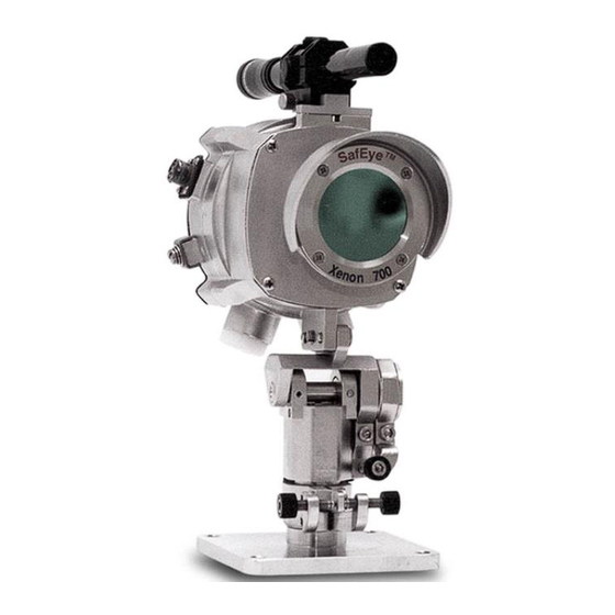
Spectrex SafEye Xenon 700S User Manual (80 pages)
Open-Path Gas Detection System
Brand:
Spectrex
| Category:
Measuring Instruments
| Size: 2 MB
Table of Contents
Legal Notice
3
Release History
4
Table of Contents
5
About this Guide
13
Abbreviations and Acronyms
14
1 Scope
15
Product Overview
15
2 Technical Description
17
Features
17
Applications
18
Principles of Operation
18
Definitions of Terms
18
Table 1: Gas Concentrations Measurement Terms
18
Spectral Finger Print
19
Optical Path
19
Microprocessor Based
19
Gas Sensitivity
19
Gas and Mixture Selection and Setting
20
Flash Source
20
Table 2: Gas Calibrations
20
Heated Optics
21
HART Protocol
21
Modbus RS-485
21
Tilt Mount
22
Product Marking
22
Models and Types
22
Table 3: Model Numbers and Installation Distances
22
Figure 1: Wiring Options
24
Description
25
Flash Source Unit
25
Figure 2: Flash Source Unit
26
Detector Unit
27
Table 4: Detector Types
27
Figure 3: Detector Unit
28
3 Operating Modes
29
Operational Modes
29
Normal Mode
29
Maintenance Call Mode (3Ma Output)
30
Fault Mode
30
Zero Calibration Mode (1Ma Output)
30
Output Signals
31
Standard 0-20Ma Current Output
31
Table 5: Standard (Default) 0-20Ma Current for the Gas Channel
31
Dry Contact Relays
32
RS-485 Interface
32
Table 6: Optional - Discrete Reading of 0-20Ma at Different Detector Modes
32
System Setup
33
Detection Function Programming
33
Detection Setup Function
33
Table 7: Sensitivity Levels Options
34
Table 8: Other Functions
34
Default Detector Setup
35
Table 9: Detector Default Setup
35
Table 10: Source Default Setup
36
4 Technical Specifications
37
General Specifications
37
Table 11: Detection Distance Range
37
Electrical Specifications
38
Power Consumption
38
Electrical Input Protection
38
Electrical Interface
38
Table 12: Detector and Source Maximum Power Consumption
38
Electrical Outputs
39
Table 13: Dry Contact Relays
39
Mechanical Specifications
40
Environmental Specifications
41
High Temperature
41
Low Temperature
41
Humidity
41
Salt and Fog
41
Water and Dust
41
Shock and Vibration
42
Electromagnetic Compatibility (EMC)
42
5 Installation Instructions
43
Introduction
43
General Considerations
43
Personnel
43
Tools Required
44
Site Requirements
44
The Source and Detector
44
General Considerations
44
Tips for Selecting a Gas Detector Location
45
Preparations for Installation
45
Preparing for Installation
46
Conduit/Cable Installation
46
Detector/Source Mounting
46
Tilt Kit
47
Detector/Source Installation
47
Table 14: Tilt Mount Kit
47
Detector Wiring
48
Figure 4: Tilt Mount
49
Table 15: Tilt Mount Description
49
Figure 5: Detector and Tilt Mount Assembly
50
Table 16: Detector and Tilt Mount Assembly Description
50
Figure 6: Detector with Cover Removed
51
Table 17: Detector with Cover Removed Description
51
Detector Terminal Wiring
52
Table 18: Wiring Options
52
Flash Source Wiring
53
Wiring
53
Terminal Wiring
53
Figure 7: Source with Cover Removed
54
Table 19: Source with Cover Removed Description
54
6 Operating Instructions
55
Safeye Operation
55
Alignment of Unit
55
Alignment of Unit
56
Powering up the System
57
Safety Precautions
57
Signal Verification
57
Signal Values Limitation
58
Zero Calibration
58
Table 20: Maintenance Channels Limited Values
58
Figure 8: Magnetic Mode Selector
59
Functional Check
60
7 Maintenance Instructions
61
General Maintenance
61
Periodic Maintenance
61
Routine Optical Surface Cleaning
62
Signal Verification
62
Functional Check of Unit
62
8 Troubleshooting
63
Troubleshooting Problems
63
Table 21: Troubleshooting Problems
63
Appendix A: Wire Selection Tables
65
General Instructions for Electrical Wiring
65
Table 22: Maximum DC Resistance at 68˚F/20˚C for Copper Wire
65
Table 23: Wiring Length in Feet/Meters
66
Appendix B: Wiring Option Configurations
67
Figure 9: Wiring Option 1
67
Figure 10: Wiring Option 2
68
Figure 11: Wiring Option 3 (Default)
69
Figure 12: 0-20Ma Wiring (Sink) for Wiring Options 1 and 3
69
Figure 13: 0-20Ma Wiring (Source) for Wiring Options 1 and 3
70
Figure 14: 0-20Ma 3 Wire Connection for Options 1 and 3
70
Figure 15: RS-485 Networking for Wiring Option 3
71
RS-485 Communications Network
71
Appendix C: Accessories
73
Tilt Mount
73
Pole Mount (U-Bolt 4-5")
73
Pole Mount (U-Bolt 2-3")
73
Wall Mount
73
HART Handheld Diagnostic Unit
74
USB/RS-485 Harness Converter Kit
74
Commissioning Kit
74
Weather Cover for the Source Unit
74
Weather Cover for the Detector Unit
74
Mini Laptop Kit
75
Appendix D: SIL-2 Features
77
Safety Relevant Parameters
77
Guidelines for Configuration, Installation, Operation, and Maintenance
77
Conditions for Safe Operation
77
Alarm Operation Using the 0-20Ma Signal Current
78
Relay Outputs
78
Miscellaneous
78
Technical Support
80
Advertisement
Advertisement
Related Products
Spectrex SharpEye 777670
Spectrex SharpEye 777915 Series
Spectrex SharpEye 777915-1
Spectrex SharpEye 777915-2
Spectrex SharpEye 777915-4
Spectrex SharpEye 777915-5
Spectrex SharpEye 777915-7
Spectrex SharpEye 777915-6
Spectrex SharpEye 777915-8
Spectrex 789260-2
Spectrex Categories
Security Sensors
Gas Detectors
Switch
Smoke Alarm
Measuring Instruments
More Spectrex Manuals
Login
Sign In
OR
Sign in with Facebook
Sign in with Google
Upload manual
Upload from disk
Upload from URL