Advertisement
Quick Links
EN
Operation and installation manual
KNX IP Interface 731
(Art. # 5242)
Compact bus powered Interface between LAN/Ethernet and KNX Bus
KNX IP Interface 731
Application
The KNX IP Interface 731 serves as a universal interface for PC
or Laptop to the KNX bus. The KNX bus can be accessed from
any point on the LAN. The KNX IP Interface 731 can be used as
a programming interface for ETS® from ETS 3.0f. For access via
KNXnet/IP Tunneling max. 5 simultaneous connections are
possible.
The IP address can be obtained by a DHCP server or by manual
configuration (ETS) respectively. Power is supplied via the KNX
bus.
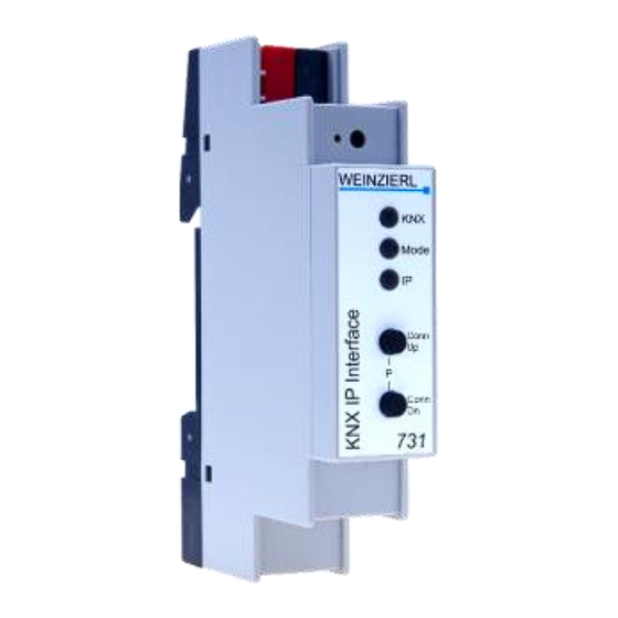
Installation and Connection
The KNX IP Interface 731 is designed for installation on a DIN
rail with a width of 1 unit (18mm). It features the following con-
trols and displays:
❶
❷
❸
❹
❺
❻
❼
❽
❾
The KNX IP Interface 731 is powered by the KNX bus. An exter-
nal power supply is not necessary.
The device is not working without KNX bus power.
KNX programming mode
The KNX programming mode is activated/deactivated either by
pressing the flushed KNX programming button
neously pressing the buttons
©2016 WEINZIERL ENGINEERING GmbH
KNX Bus Connector
LED for Programming Mode (red)
Button for Programming Mode
LED KNX (red/green)
LED Mode (red/green)
LED IP (red/green)
Button Connection up
Button Connection down
Ethernet/LAN Connector
❸
or by simulta-
❼
❽
and
.
Status display
❹
The KNX LED
lights up green if the device is successfully
powered by the KNX bus. The LED indicates telegrams on the
KNX bus by flickering.
Communication failures (e.g. repetitions of telegram or telegram
fragments) are indicated by a short change of the LED color to
red.
❻
The IP LED
lights up when an Ethernet link is active. This
LED is green if the device has valid IP settings (IP address, Sub
net and Gateway). With invalid or nonexistent IP settings the
LED is red. This is also the case if e.g. the device has not yet
received the IP settings by a DHCP server. The LED indicates IP
telegrams by flickering.
❺
The Mode LED
can visualize the status of each KNXnet/IP
tunneling connection. With the buttons Conn Up/Dn
can chose each single connection. Conn Up
connection numbers up and Conn Dn
selected connection number is indicated by flashing (1x...5x) of
❺
the Mode LED
. An available KNXnet/IP Tunneling connec-
tion is indicated by a green LED and a used tunneling connec-
tion is indicated by an orange LED.
Via the Escape function (Esc) this indication can be ended by
simultaneously pressing the buttons Conn Up/Dn
If neither programming mode nor manual operation are active
❺
the Mode LED
can visualize configuration errors.
Overview of the different indications of the Mode LED:
LED Status
Meaning
LED lights green
Device is working in standard operation mode.
LED lights red
Programming mode is active
Programming mode is not active.
Manual operation is active.
LED flashes green 1x..5x
The selected tunnel (1-5) is not used and free
Programming mode is not active.
Manual operation is active.
LED flashes orange 1x...5x
The selected tunnel (1-5) is used
Programming mode is not active.
Manual operation is not active.
LED flashes red
The device is not properly loaded e.g.
after an interrupted download.
Factory default settings
Factory default configuration:
Individual device address:
Number of configured KNXnet/IP tunneling con.: 1
Individual address of tunneling con.:
IP address assignment:
Reset to factory device settings
It is possible to reset the device to its factory settings:
Separate the KNX Bus connector
Press the KNX programming button
pressed down
Reconnect the KNX Bus connector
Keep the KNX programming button
least another 6 seconds
❼ ❽
you
❼
counts the
❽
down. The actually
❼ ❽
.
15.15.255
15.15.250
DHCP
❶
from device
❸
and keep it
❶
of device
❸
pressed for at
Page 1/4
Advertisement

Related Manuals for Weinzierl KNX IP Interface 731


Summary of Contents for Weinzierl KNX IP Interface 731
- Page 1 Conn Dn down. The actually any point on the LAN. The KNX IP Interface 731 can be used as selected connection number is indicated by flashing (1x…5x) of a programming interface for ETS® from ETS 3.0f. For access via ❺...
- Page 2 Example: By clicking on the KNX IP Interface 731 device entry within your Device address 1.1.10 (address within ETS topology) ETS projects topology view, an information column ‘Properties’...
- Page 3 Subnet of the PC: 255.255.255.0 The KNX IP Interface 731 is located in the same local LAN, i.e. it uses the same subnet. The subnet constrains the IP addresses that can be assigned. In this example, the IP address of the IP interface must be 192.168.1.xx, where xx can be a number from...
- Page 4 The prevailing safety rules must be heeded. The device must not be opened. The KNX IP Interface 731 supports up to 5 simultaneous con- nections. For each connection a separate individual address is For planning and construction of electric in- used.
Need help?
Do you have a question about the KNX IP Interface 731 and is the answer not in the manual?
Questions and answers