Advertisement
DR5013 DIGIREVERSE
Instruc on manual
© Copyright 2005 – 2018 digikeijs, the Netherlands. All
rights reserved. No informa3on, images or any part of
this document may be copied without the prior wri4en
permission of Digikeijs.
www.digikeijs.com
® R-Bus, B-Bus are trademarks which are registered in the name of Modelleisenbahn GmbH. XpressNet and RS-Bus is a trademark registered in the name of Lenz
Stand 2019.01.06
DR5013
DIGIREVERSE
(2019.01.06)
P 1
Advertisement

Related Manuals for Digikeijs DR5013 DIGIREVERSE


Summary of Contents for Digikeijs DR5013 DIGIREVERSE
- Page 1 Stand 2019.01.06 DR5013 DIGIREVERSE Instruc on manual (2019.01.06) © Copyright 2005 – 2018 digikeijs, the Netherlands. All rights reserved. No informa3on, images or any part of this document may be copied without the prior wri4en permission of Digikeijs. www.digikeijs.com ® R-Bus, B-Bus are trademarks which are registered in the name of Modelleisenbahn GmbH. XpressNet and RS-Bus is a trademark registered in the name of Lenz...
-
Page 2: Table Of Contents
DR5013 DIGIREVERSE Stand 2019.01.06 1 General Informa on 1 Index General informa on DR5013 Connec3on with sensor tracks (S1,S2) with Index LocoNet Warranty and warranty condi3ons DR5013 Connec3on with sensor tracks (S1,S2) without LocoNet® Legal informa3on External feedback connec3on Product overview General product informa3on Technical Specifica3ons... - Page 3 We reserve the right to change the design of the product, the so?ware and / or the firmware without prior no3ce. Copyright All Digikeijs opera3ng instruc3ons and other wri4en instruc3ons supplied and/or downloadable are protected by copyright. Reproduc3on is not permi4ed without the wri4en permission of Digikeijs.
-
Page 4: Product Overview
DR5013 DIGIREVERSE Stand 2019.01.06 2.0 Product overview 2.1 General product informa on The DR5013 operates either with sensor tracks (short-circuit-free) or via "short-circuit detec3on" to switch over the reversing loop. The polarity of the reversing loop can also be changed via a switch command. The busy signal of the sec3ons (T, S1, S2) can be done via LocoNet® or external output (for GND or CS feed- back). -
Page 5: Hardware Overview
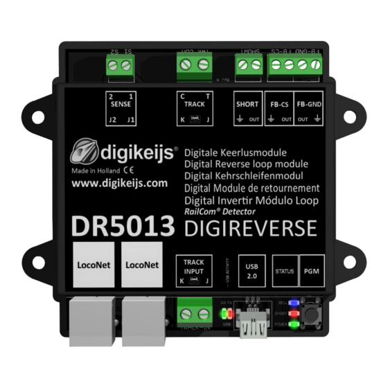
DR5013 DIGIREVERSE Stand 2019.01.06 2.3 Hardware Overview 9 10 1 Sensor track 2 2 Sensor track 1 3 Track C (Railcom® Detector and Feedback Reverse Loop) 4 Track T (Railcom® Detector and Feedback Reverse Loop) Short Feedback 6 Short Feedback external Short circuit detected FB-CS Track "Ground"... -
Page 6: Programming
DR5013 DIGIREVERSE Stand 2019.01.06 3.0 CONFIGURATION SOFTWARE ATTENTION!!!! NEVER connect the DR5013 to the PC via USB when the TRACK INPUT of the DR5013 is connected to the TrackOut (main track or programming track) of the central unit! This can destroy the DR5013, the central unit and/or the USB interface in the PC. - Page 7 3.2 Download So&ware Do not connect the DR5013 to the PC un3l the so?ware has been installed. The so?ware can be downloaded from the DIGIKEIJS website. www.digikeijs.com ® R-Bus, B-Bus are trademarks which are registered in the name of Modelleisenbahn GmbH. XpressNet and RS-Bus is a trademark registered in the name of Lenz...
- Page 8 DR5013 DIGIREVERSE Stand 2019.01.06 3.3 Install so&ware A?er you have successfully downloaded the so?ware, the installa3on can be started by double-clicking on the DR5013xx.exe file. Make sure that you have administrator rights on your PC. Important !!! Do not connect the DR5013 to the PC un3l the so?ware and driver have been successfully installed.
- Page 9 DR5013 DIGIREVERSE Stand 2019.01.06 The following screen appears a?er a few seconds. Click "Next". If you want to change the loca3on of the so?ware, you can do so on the next screen. However, it is recommended to leave the seBngs as they are and click "Next".
- Page 10 DR5013 DIGIREVERSE Stand 2019.01.06 Now follows a short overview of the seBngs. Click on "Install" if you agree. Now the configura3on so?ware will be installed and Windows will ask you a few 3mes if you trust Digikeij's so?ware. When all this is complete, the last screen appears. Press "Finish" and the drivers and configura3on program are installed.
- Page 11 DR5013 DIGIREVERSE Stand 2019.01.06 3.4 Connec ng the DR5013 to the PC via USB With the desktop symbol the so?ware can be started. Do not start the so?ware un3l the following steps have been performed! First connect the PC with the supplied USB cable and then with the DR5013.
- Page 12 DR5013 DIGIREVERSE Stand 2019.01.06 4.0 Programming All pictures shown here usually show the factory se@ngs of the DR5013. However, some pictures show more informa on than is available in the factory se@ngs, which has the reason to clarify which op3ons and seBngs are available in the DR5013.
-
Page 13: Usb Features
DR5013 DIGIREVERSE Stand 2019.01.06 4.1 Overview Configura on So&ware The various op3ons can be easily accessed by clicking on the respec3ve connec3ons. 1 Proper3es of sensor tracks 2 Features Global Detector 3 USB Features / Firmware Upgrade 4 Exit so?ware... - Page 14 DR5013 DIGIREVERSE Stand 2019.01.06 4.2 USB 2.0 Features The selected DR5013 has been connected via USB and the serial number is read. COM port number for the Dr.Command protocol. Update the firmware of the DR5013. Reset to factory seBngs. Cancel www.digikeijs.com...
- Page 15 DR5013 DIGIREVERSE Stand 2019.01.06 4.3 Restoring the factory se@ngs It is possible to reset the DR5013 seBngs to the factory defaults. The USB menu in the configura3on so?ware allows you to ac3vate the reset, which resets the DR5013 seBngs to factory defaults.
- Page 16 DR5013 DIGIREVERSE Stand 2019.01.06 4.4 Upda ng the So&- and Firmware The development of the DR5013 so?ware con3nues and is constantly being improved. With firmware updates, you can equip the DR5013 with the latest so?- ware. The new firmware is integrated in a new configura3on so?ware. Before a firmware update is performed, it is recommended to save the current seBngs using the "Import/Export SeBngs"...
-
Page 17: Firmware Versions
DR5013 DIGIREVERSE Stand 2019.01.06 4.5 Firmware Versions Version date Beschreibung 1.0.0 01.11.2018 First beta version for beta testers 1.0.0 10.10.2018 First instruc3ons 1.0.0 11.11.2018 Connec3on examples www.digikeijs.com ® R-Bus, B-Bus are trademarks which are registered in the name of Modelleisenbahn GmbH. XpressNet and RS-Bus is a trademark registered in the name of Lenz... -
Page 18: Loconet® Features
DR5013 DIGIREVERSE Stand 2019.01.06 4.5 LocoNet® Features LocoNet® Feedback Monitor. The different colors indicate the different feedback busses. Slow Module Timing This op3on can be ac3vated if there are problems with Loconet. RailCom Report. Here you select which LocoNet commands are used to send the RailCom message. - Page 19 DR5013 DIGIREVERSE Stand 2019.01.06 4.6.0 Modul Eigenscha&en Display Logging Window. 11) Module SeBng Export/Import Select language. 12) Accept current seBngs Module address in LocoNet®. 13) Cancel Wai3ng 3me a?er the central unit has transmi4ed power on before the track 14) Railcom® Use channel 2 for addi3onal address recogni3on.
- Page 20 DR5013 DIGIREVERSE Stand 2019.01.06 4.6.1 Module Proper es Digitrax® specifica3on for repor3ng 'short' locomo3ve addresses. All QoS messages below this value are not reported to the central Standard: Report 0x7D in high quality byte. unit. Alterna3ve: Report 0x00 in high quality byte.
- Page 21 DR5013 DIGIREVERSE Stand 2019.01.06 4.7 Scrip ng DR. Script DR Script is a BASIC / Assembler similar, text based programming language. With Dr. Script you have the possibility to control even complex processes with the help of a product of the DR50xx series. Further informa3on about Dr. Script can be found in the separate documenta3on.
- Page 22 DR5013 DIGIREVERSE Stand 2019.01.06 4.8 Proper es of sensor tracks The proper3es of the sensor tracks and the feedback number are assigned to the reversing loop here. Switch-off delay Feedback in ms. turnout address Entrance turnout of the reversing loop...
- Page 23 DR5013 DIGIREVERSE Stand 2019.01.06 4.9 Features Global Detector Here the proper3es of the Global Detector are assigned to the reversing loop. The Global Detector comprises the sec3ons S1, S2 and T of the reversal loop. Detector input on the module. (If a check mark is removed here, the corresponding detector is deac3vated).
-
Page 24: Connec On Examples
DR5013 DIGIREVERSE Stand 2019.01.06 5.0 Connec on examples In the 2-wire system, different polari3es of the tracks meet at the turnout of the reversing loop. If a vehicle now bridges the separa3on points at the en- trance or exit, a short circuit occurs. The ul3mate DR5013 reversing loop module can be used to eliminate this problem. The connec3on examples shown here give an overview of how the DR5013 can be wired in different situa3ons and which seBngs are necessary in the configura3on so?ware. -
Page 25: External Feedback Connec3On
DR5013 DIGIREVERSE Stand 2019.01.06 5.1 Connec on DR5013 Short-circuit detec on This connec3on example shows the use of the DR5013 with short-circuit detec3on. The entry/exit switch must be switched manually or with a control program. Func onality: As soon as the locomo3ve reaches the separa3on point on both sides, the DR5013 detects this and switches the polarity of the reversing loop so that it cor- responds to the entrance. - Page 26 DR5013 DIGIREVERSE Stand 2019.01.06 5.2 DR5013 short circuit detec on and LocoNet® connec on® This connec3on example shows the use of the DR5013 with short-circuit detec3on. The entry/exit turnout must be switched manually or with a control program. Via Lo- coNet®...
- Page 27 DR5013 DIGIREVERSE Stand 2019.01.06 5.3 Connec on DR5013 with sensor tracks (S0,S1,S2,S3) and LocoNet® This connec3on example shows the use of the DR5013 in conjunc3on with sensor tracks (S0,S1,S2,S3). With this connec3on, the DR5013 automa3cally reverses the polarity (short- circuit-free) and may be able to switch the entry/exit switch automa3cally on exit. LocoNet® transmits various informa3on (Railcom® informa3on, feedback, short-circuit message, etc.) to the control centre and can be evaluated accordingly.
- Page 28 DR5013 DIGIREVERSE Stand 2019.01.06 5.4 DR5013 connec on with sensor tracks (S1,S2) and LocoNet This connec3on example shows the use of the DR5013 in conjunc3on with sensor tracks (S1,S2). With this connec3on, the DR5013 automa3cally reverses the polarity (short-circuit -free) and may be able to switch the entry/exit switch automa3cally on exit. Via LocoNet® various informa3on (Railcom® informa3on, feedback, short-circuit message, switch seBng commands, etc.) is transmi4ed to the central unit and can be evaluated accordingly.
- Page 29 DR5013 DIGIREVERSE Stand 2019.01.06 5.5 DR5013 connec on with sensor tracks (S1,S2) without LocoNet® This connec3on example shows the use of the DR5013 in conjunc3on with sensor tracks (S1,S2). The occupied signal of the KS is transmi4ed via an external feedback unit, in this case a DR4088CS.
- Page 30 DR5013 DIGIREVERSE Stand 2019.01.06 5.6 DR5013 external feedback connec on The DR5013 has three external feedback outputs. With these feedback outputs, the busy signal of the reversing loop (FB current sensor, GND signal to ground) and a short circuit signal of the reversing loop can be reported to an external feedback.
Need help?
Do you have a question about the DR5013 DIGIREVERSE and is the answer not in the manual?
Questions and answers