Table of Contents
Advertisement
Quick Links
Advertisement
Table of Contents

Related Manuals for Nemco 6900 Series


Summary of Contents for Nemco 6900 Series
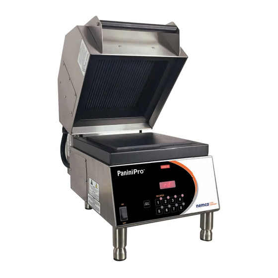
- Page 1 SERVICE MANUAL 6900-( )-( ) HIGH SPEED SANDWICH PRESS...
- Page 2 CAUTION PRECAUTIONS TO BE OBSERVED BEFORE AND DURING SERVICING TO AVOID POSSIBLE EXPOSURE TO EXCESSIVE MICROWAVE ENERGY (a) Do not operate or allow the oven to be operated with the door open. (b) Make the following safety checks on all ovens to be serviced before activating the magnetron or other microwave source, and make repairs as necessary: (1) interlock operation.
-
Page 3: Electrical Installation
ELECTRICAL INSTALLATION For all cord connected appliances: GROUNDING INSTRUCTIONS This appliance must be grounded. In the event of an electrical short circuit, grounding reduces the risk of electric shock by providing an escape wire for the electric current. This appliance is equipped with a cord having a grounding wire with a grounding plug. -
Page 4: Safety Instructions
SAFETY INSTRUCTIONS PLEASE READ THIS ENTIRE PAGE BEFORE BEGINNING ANY SERVICE ACTIVITES This manual is to assist the authorized service agent that has been trained by NEMCO on the proper service procedures for this appliance. If at any time the service agent is unsure how to properly or safely service the sandwich press; they should contact NEMCO immediately for instructions. -
Page 5: Product Specifications
PRODUCT SPECIFICATIONS Model Number: 6900-VVV-CC Supply Frequency Supply Customer Country Voltage 208 = 208V 60 Hz L1+L2+Gnd (US 30A Plug) GM=General US/Canada L1+L2+Gnd (Canada 50A Plug) Market 240 = 240V L1+L2+Gnd (US/Canada 30A Plug) Power 208V or 208V 60Hz 28Amps 240V 240V 60Hz 24Amps Power Output... -
Page 6: Installation Instructions
INSTALLATION INSTRUCTIONS Power Supply Requirements The sandwich press MUST be connected to a properly grounded receptacle that is correctly rated for the current listed on the device’s product label or MUST be hard-wired to the supply with a proper ground. The sandwich press should be connected to its own power circuit (Type C or Time Delay circuit breaker). - Page 7 6. Specification Plate – This plate shows the ratings for this device along with, model & serial number, and NEMCO contact information. 7. USB Port – This port is used to load menu files with an approved USB flash drive.
-
Page 8: Control Features
CONTROL FEATURES POWER SWITCH – Toggle switch to “ON” to energize the control. Turning the switch to “OFF” will power down the control and cancel any menu. MENU BUTTONS – Pressing any of the menu buttons will cause the red circle next to the corresponding button to illuminate. -
Page 9: Component Locations
COMPONENT LOCATIONS UPPER CAVITY MAGNETRONS - MAGNETRON HIGH LIMIT SWITCHES - HEATER PLATE RELEASE MECHANISM & HEIGHT ADJUSTMENT COLLAR MAGNETRON COOLING FANS - UPPER HEATER PLATE THERMOCOUPLE CONNECTION... - Page 10 REAR ENCLOSURE ELECTROMAGNET - MAGENT SWITCH – PRIMARY, SECONDARY, & INTERLOCK SWITCHES – LID SPRINGS – LID DAMPENER – GAS SHOCK...
- Page 11 LOWER ENCLOSURE LINE FUSES (30A) – INTERLOCK FUSE (20A) CONTROL BOARD – BUZZER – 12V TRANSFORMER – HIGH LIMIT THERMOSTAT (MANUAL RESET) – FUSE, CONTROL BOARD (3A) – HEATER PLATE THERMOCOUPLE CONNECTIONS – POWER SWITCH...
- Page 12 HIGH VOLTAGE TRANSFORMERS – COOLING FAN CAPCITORS - DIODES...
- Page 13 Microwave emission testing must be performed after this appliance is serviced. The emission should be less than 5mW/cm2; contact NEMCO if the emissions is higher than 5mW/cm2. Written records must be taken of repairs made and of the emission readings that were taken to fulfill the requirements set by the DHHS and Canada’s Health and Welfare regulation.
-
Page 14: Component Testing
COMPONENT TESTING (Page 1) WARNING The microwave circuit in this appliance is extremely dangerous. DO NOT take any voltage measurements from the magnetron, HV capacitor, HV transformer, or filament transformer while the sandwich press is running. Doing so could result in serious injury or DEATH! WARNING The HV capacitors hold a high voltage charge even when the appliance is not running a menu cycle and for a short period of time after the sandwich press is unplugged. - Page 15 COMPONENT TESTING (Page 2) WARNING The microwave circuit in this appliance is extremely dangerous. DO NOT take any voltage measurements from the magnetron, HV capacitor, HV transformer, or filament transformer while the sandwich press is running. Doing so could result in serious injury or DEATH! WARNING The HV capacitors hold a high voltage charge even when the appliance is not running a menu cycle and for a short period of time after the sandwich press is unplugged.
- Page 16 COMPONENT TESTING (Page 3) WARNING The microwave circuit in this appliance is extremely dangerous. DO NOT take any voltage measurements from the magnetron, HV capacitor, HV transformer, or filament transformer while the sandwich press is running. Doing so could result in serious injury or DEATH! WARNING The HV capacitors hold a high voltage charge even when the appliance is not running a menu cycle and for a short period of time after the sandwich press is unplugged.
- Page 17 DOOR INTERLOCK SWITCH ADJUSTMENT (P. 1) The microwave circuit goes through an interlock switch system of 2 interlock switches and 1 monitor switch that prevents the generation of microwaves when the upper enclosure is open. Primary and Secondary Interlock Switches All of the L1 line voltage for the microwave circuits goes through the primary and secondary switches.
- Page 18 DOOR INTERLOCK SWITCH ADJUSTMENT (P. 2) MONITOR SWITCH PRIMARY SWITCH SECONDARY SWITCH 1. Disconnect the press from the power supply. 2. Loosen (2) screws on each of the switch brackets. 3. Place a ½” spacer on the front ledge of the press and pull down the lid. 4.
-
Page 20: Troubleshooting Guide
TROUBLE SHOOTING GUIDE SYMPTOM POSSIBLE CAUSE No power Check to ensure press is plugged in. Check wall receptacle for power & proper voltage. Check 30A line fuses. Press has power, but Check 3A control board fuse. board is not lit Check manual reset high limit thermostat.
Need help?
Do you have a question about the 6900 Series and is the answer not in the manual?
Questions and answers