
Subscribe to Our Youtube Channel
Summary of Contents for Lnk SoundWire
- Page 1 SoundWire Analyzer User Manual 44, rue des Combattants B-4624 Romsée Belgium www.lnk-tools.com info@lnk-tools.com SoundWire Protocol Analyzer User Manual V1.0...
-
Page 2: Table Of Contents
1. HARDWARE SPECIFICATION 1.1. Hardware dimension 1.2. User Interface 1.3. Connectivity 1.3.1. SoundWire bus connector 1.3.2. Multi-purpose connector 1.3.2.1. GPI operation 1.3.2.2. Serial Audio Interface 1.3.3. Clock input and output connectors 1.3.4. Monitoring Signals connector 1.3.5. USB3 connector 1.3.6. Power supply connector 1.4. - Page 3 6. Data Samples 7. Port Registers 8. Stream Mapping SoundWire Protocol Analyzer User Manual V1.0...
- Page 4 SoundWire Protocol Analyzer User Manual V1.0...
-
Page 5: Hardware Specification
1. HARDWARE SPECIFICATION SoundWire Protocol Analyzer User Manual V1.0... -
Page 6: Hardware Dimension
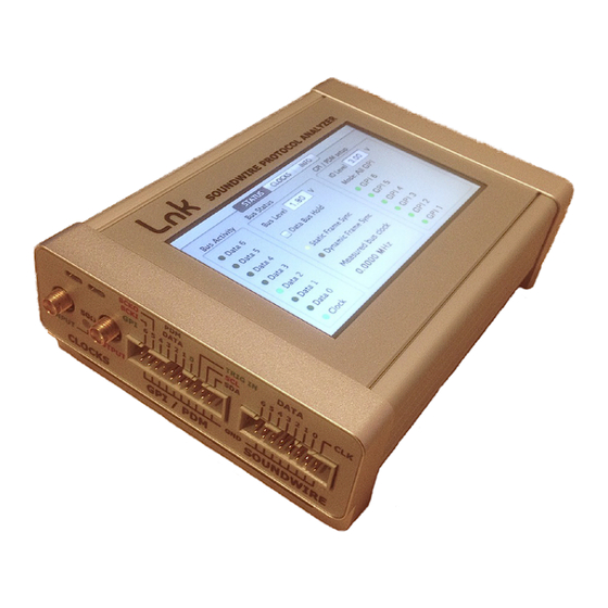
TRIG IN DATA BCKI 1 2 3 4 5 6 INPUT OUTPUT CLOCKS GPI / PDM SOUNDWIRE (left) DATA DIFF USB3 TRIG OUT 1 DATA TRIG OUT 2 STBY (right) 9..12 VDC MONITORING SIGNALS SoundWire Protocol Analyzer User Manual V1.0... -
Page 7: Soundwire Bus Connector
1.3.1. SoundWire bus connector The SoundWire signals (clock and data) are available on a boxed IDC 16 pin header connector with a regular pitch of 2.54 mm (0.1”). The bottom pins are all connected to ground. Signal Direction Clock Input & output Data Line 0 (main) Input &... -
Page 8: Gpi Operation
The interface is always a clock master because clocks are either directly derived from the SoundWire bus clock or generated from an external audio master clock. The Serial Audio Interface supports PDM and PCM streaming on up to 4 data lines. - Page 9 ) is equal to 13.6 ns. The delay between CHA_EN the clock rising edge and the data edge (T ) is equal to 12.5 ns. The data line is sampled on CHB_EN the every clock edge. SoundWire Protocol Analyzer User Manual V1.0...
- Page 10 Ch 5 Port Sink Ch 5 SDO3 DATA ROUTER Port Ch 6 Ch 6 DATA ROUTER SDO3 Ch 7 SDO4 Ch 7 Ch 8 DATA ROUTER SDO4 DATA ROUTER Ch 8 Control Registers Control Registers SoundWire Protocol Analyzer User Manual V1.0...
-
Page 11: Clock Input And Output Connectors
1.3.3. Clock input and output connectors The unit can input an external clock to feed the SoundWire Traffic Generator. It can also output a configurable clock. The connectors are 50 Ohms SMA. The input impedance is configurable and can be set to 50 Ohms or 1MOhms. The 50 Ohms state is indicated by a glowing yellow led close to the input connector. -
Page 12: Monitoring Signals Connector
The buffered SoundWire clock signal is a copy of the captured SoundWire clock. It enables scope probing without disturbing the bus. The buffered SoundWire data signal is a copy of one of the 7 SoundWire data lines. The selected line is control through a script command or directly via the PC application. -
Page 13: Usb3 Connector
4 Ch PDM in and 4 Ch PDM out 8 Channel PDM outputs 8 Channel PCM inputs 8 Channel PCM outputs The operation mode is indicated as well as the bit and word clocks (from release 1.27 and upwards). SoundWire Protocol Analyzer User Manual V1.0... -
Page 14: Soundwire I/O
This part of the display shows the measured bus frequency, the status of the bus hold and the SoundWire signalling voltage. When activity is detected on a pin, the display shows a yellow circle in place of the corresponding pin (grey by default). -
Page 15: Software Operation
Note that it’s always a good practice to copy the latest software release on the provided USB memory stick. Once the installation is finished, go to the windows menu Program (in the task bar) and select LnK SoundWire Tools. •... - Page 16 HW not present or non configured HW detected and being configured HW detected and configured SoundWire Protocol Analyzer User Manual V1.0...
-
Page 17: Load A Script In The Traffic Generator
Load an XML script from the traffic generator itself (though File menu or by pressing the Script button) Push it directly from the script editor (use CTRL+T or press the button Send to TG in the Finalize window). The script content is shown in the main analyzer window. SoundWire Protocol Analyzer User Manual V1.0... -
Page 18: Play And Record A Script
First press the REC button. Once pressed, it is greyed out. The analyzer is waiting for any clock activity on SoundWire to start the recording process. It’s possible to stop the recording at any moment by pressing the STOP button besides the REC button. The amount of recorded data is shown in the status bar, on the bottom left side of the window. -
Page 19: Recording Options
But the capturing of the messages is allowing to build up the configuration and show all detected data port and device configurations. SoundWire Protocol Analyzer User Manual V1.0... -
Page 20: Stream Analysis
3. Stream analysis The protocol analyzer software offers various levels of reading of the captured SoundWire bit stream. 3.1.1. Message View The Message View has multiple levels of analysis: SoundWire Protocol Analyzer User Manual V1.0... - Page 21 Errors. All frames that are obtaining errors are listed here. That is easy to navigate to a certain error and then switch back to a more generic view such as Application view. Enumeration. Here all enumeration related events are shown. SoundWire Protocol Analyzer User Manual V1.0...
- Page 22 Interrupt. Only interrupt related events are shown. Search. This is a text based search with the following keywords or combinations: write, read, ping, da=1, da=0x1, ra=304, ra=0x0130, data=3, data=0x03, ack=1, nak=0, bank, ssp, slavestatus=changed, preq, reset, error, bus_reset SoundWire Protocol Analyzer User Manual V1.0...
-
Page 23: Raw View
The first column contains the control word. If bit slots with a ‘1’ value are detected in unconfigured data space they are coloured red to flag an error. SoundWire Protocol Analyzer User Manual V1.0... -
Page 24: Data View
The main purpose of the DATA View to to show the configuration and content of the different data streams active on the SoundWire bus at a given moment in time. Up to 7 configured data ports are mapped onto the data port selection buttons together with a user “Data Config”... - Page 25 Frame Shape: Shows the frame shape on an alternating background color. ex 2x48 GPI: General Purpose Inputs are shows as defined in the GPI config. As 1 line or as a bus. A system or data port register values are displayed over the time line SoundWire Protocol Analyzer User Manual V1.0...
-
Page 26: Info Notebook
A general memory map shows the complete 64K range and also the different data port and system area are selectable together with eventual define regions of specific devices. See component editor of script builder, RAW mode: SoundWire Protocol Analyzer User Manual V1.0... -
Page 27: Device Mapping
Decoded mode indicates the name of the register and has all the bit fields explained as written in the SoundWire specification so it is clear what was written to or read from that register. When A component has defined in the component library (via script builder or xml) then specific regions are added to the choice list. -
Page 28: Ports Mapping
If a full recording has been done or a *.swa or *.fvf has been loaded, the content is dynamically updated according to the position of the time line cursor. When the analyzer is in live view, the page is showing the current situation of the bus. SoundWire Protocol Analyzer User Manual V1.0... - Page 29 If a full recording has been done or a *.swa or *.fvf has been loaded, the content is dynamically updated according to the position of the time line cursor. When the analyzer is in live view, the page is showing the current situation of the bus. SoundWire Protocol Analyzer User Manual V1.0...
Need help?
Do you have a question about the SoundWire and is the answer not in the manual?
Questions and answers