Table of Contents
Advertisement
Quick Links
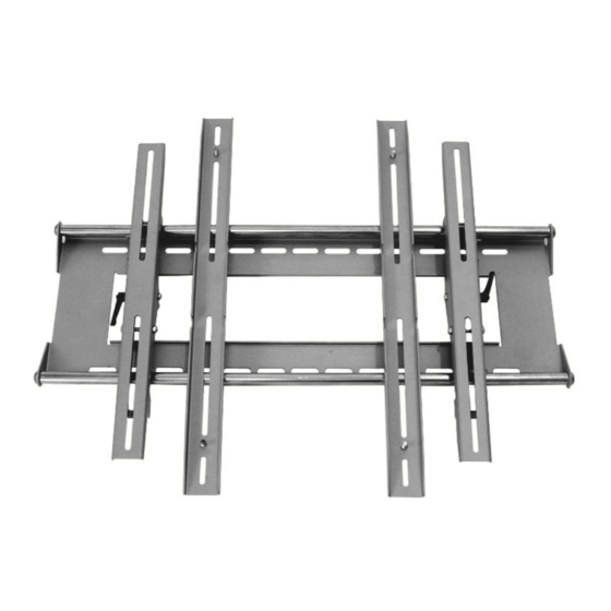
Large Universal Premium Tilt Flat Panel Mount
Hardware List:
Hardware Kit 1
Letter
Qty
Description
A
4
Philips Screws M4 x 16mm, Zinc
B
4
Philips Screws M4 x 36mm, Zinc
C
4
Philips Screws M5 x 16mm, Zinc
D
4
Philips Screws M5 x 36mm, Zinc
E
4
Philips Screws M5 x 46mm, Zinc
F
4
Philips Screws M6 x 16mm, Zinc
G
4
Philips Screws M6 x 36mm, Zinc
H
4
Philips Screws M6 x 46mm, Zinc
I
4
Philips Screws M8 x 16mm, Zinc
J
4
Philips Screws M8 x 36mm, Zinc
K
4
Philips Screws M8 x 46mm, Zinc
Hardware Kit 2
Letter
Qty
Description
L
4
Square Washer
M
4
Safety Washer; 1/2" ID
N
4
3/8" Wall Anchors
1
Push Pin
1
4
5/8" Spacer
2
4
3/4" Spacer
1
Hex wrench
4
3/8" Lag Bolt; 3 1/2" long
4
Lag Bolt Washer
Wall Plate, Mounting Rails with Tilt Mechanism, Rod Extensions, Mounting Rail Extensions
63FBHD-T P/N 1002261 - REV. D 7/2005
1
Advertisement
Table of Contents

Related Manuals for Omnimount 63FBHD-T


Summary of Contents for Omnimount 63FBHD-T
- Page 1 Wall Plate, Mounting Rails with Tilt Mechanism, Rod Extensions, Mounting Rail Extensions Safety Washer; 1/2" ID 3/8” Wall Anchors Push Pin 5/8" Spacer 3/4" Spacer Hex wrench 3/8” Lag Bolt; 3 1/2” long Lag Bolt Washer 63FBHD-T P/N 1002261 - REV. D 7/2005...
- Page 2 Determine the Mounting Location Measure the width and height dimensions of the plasma display. Mark the wall with the desired location for the center of the display. Important: Make sure that there is adequate mounting space available for the display, considering the display dimensions. The Mounting Guide Locate the supplied mounting guide.
- Page 3 Some Plasma displays have curved backs with recessed mounting lands (Fig. 4), which will require the use of a spacer (Fig. 5). For these displays, install the 5/8” (1) spacer between the display and the rail. Note: Align tab in spacer with slot in mounting rail. Top View of Plasma Fig.
- Page 4 Tilt the Display Important: Always support the upper edge of the display when adjusting the tilt angle. To adjust the tilt angle, loosen both tilt tensioning levers just enough so that the display can be moved by applying pressure to the upper edge. With the desired tilt angle set, re-tighten both tilt tensioning levers.
- Page 5 Using the Extension Rods Caution: The safety washer (M) MUST be installed whenever using the rod extensions. There are two situations for using the extension rods: 1. The horizontal distance between the mounting holes on the display, causes the mounting rails to exceed the maximum 30” (76 cm) width of the standard wall plate. (Fig. In this case, install all four of the extension rods.
Need help?
Do you have a question about the 63FBHD-T and is the answer not in the manual?
Questions and answers