Table of Contents
Advertisement
574B
SINGLE- -PACKAGED GAS FURNACE/AIR CONDITIONER
SYSTEM WITH PURONE REFRIGERANT
2- -5 NOMINAL TONS (SIZES 024- -060) 1 & 3 PHASE
NOTE:
Read the entire instruction manual before starting the
installation.
NOTE:
Installer: Make sure the Owner's Manual and Service
Instructions are left with the unit after installation.
TABLE OF CONTENTS
. . . . . . . . . . . . . . . . . . . . . . . . . . . . . . . . . .
. . . . . . . . . . . . . . . . . . . . . . . . . . . . . . . . .
. . . . . . . . . . . . . . . . . . . . . . . . . . . . . . . . . . .
. . . . . . . . . . . . . . . . . . . . . . . . . . . . . . . .
. . . . . . . . . . . . . . . . . . . . . . . . . . . . . .
. . . . . . . . . . . . . . . . . . . . . . . . . . . . . . . . . . . . .
. . . . . . . . . . . . . . . . . . . . . . . . . . . . . . . . . . . .
. . . . . . . . . . . . . . . . . . . . . . . . . . . . . . . . .
. . . . . . . . . . . . . . . . . . . . . . . . . . .
. . . . . . . . . . . . . . . . . . . . . . . . . . . . . . . .
. . . . . . . . . . . . . . . . . . . . . . . . . . . . . . . .
. . . . . . . . . . . . . . . . . . . . . . . . . . . . . . . . . .
. . . . . . . . . . . . . . . . . . . . . . . . . . . . . . . . .
. . . . . . . . . . . . . . . . . . . . . . . . . . . .
. . . . . . . . . . . . . . . . . . . . . . . . . . . . . . . . . . . . .
. . . . . . . . . . . . . . . . . . . . . . . . . . . . . . . . . .
. . . . . . . . . . . . . . . . . . . . . . . . . .
. . . . . . . . . . . . . . . . . . . . . . . . . . . . . . . . . .
. . . . . . . . . . . . . . . . . . . . . . . . . . . . . . . . . . . .
. . . . . . . . . . . . . . . . . . . . . . . . . . . . . . .
. . . . . . . . . . . . . . . . . . . . . . . . . . . . . . .
. . . . . . . . . . . . . . . . . . . . . . . . . . . .
. . . . . . . . . . . . . . . . . . . . . . . . . . . . . . . .
. . . . . . . . . . . . . . . . . . . . . . . . . . . . . . .
. . . . . . . . . . . . . . . . . . . . . . . . . . . . . . . . . . . . . . .
. . . . . . . . . . . . . . . . . . . . . . . . . . . . .
Installation Instructions
PAGE
. . . . . . . . . . . . . . . . . . . . . . . .
. . . . . . . . . . . . . . . .
. . . . . . . . . . . . . . . . . . . . . . . . . .
. . . . . . . . . . . . . . . . . . . . . . .
. . . . . . . . . . . . . . . . . . . . . . .
. . . . . . . . . . . . .
. . . . . . . . . . . . . . . . . . . . . .
. . . . . . . . . . . . . . . . . . . . . . . . .
15- -22
. . . . . . . . . . . . . . . . . . . . . . . .
. . . . . . . . . . . . . . . . . . . . . . . .
. . . . . . . . . . . . . . . . . . . . . .
. . . . . . . . . . . . . . .
. . . . . . . . . . . . . . . . . . . . . . . .
. . . . . . . . . . . . . . . . . . . . .
. . . . . . . . . . . . . . . . . .
. . . . . . . . . . . . . . .
. . . . . . . . . . . . . . .
. . . . . . . . . .
. . . . . . . . . . . .
22- -26
. . . . . . . . . . . . . . . . . . . . . . .
. . . . . . . . . . . . . . .
1
2
2- -12
2
2
2
2
2
2
2
2
4
4
7
8
9
9
9
11
11
11
12
. . . . . . . . . . . . . . . . . . . . . . . . . . . . . . . . . . . . . .
12
14
14
14
. . . . . . . . . . . . . . . . . . . . . . . . . . . . . . . . . . . . . . .
15
15
15
15
SAFETY CONSIDERATIONS
15
Installation and servicing of this equipment can be hazardous due
15
to mechanical and electrical components. Only trained and
16
qualified personnel should install, repair, or service this
16
equipment.
19
Untrained personnel can perform basic maintenance functions
19
such as cleaning and replacing air filters. All other operations
19
must be performed by trained service personnel. When working
19
19
on this equipment, observe precautions in the literature, on tags,
and on labels attached to or shipped with the unit and other safety
22
precautions that may apply.
22
Follow all safety codes. Installation must be in compliance with
23
local and national building codes. Wear safety glasses, protective
23
clothing, and work gloves. Have fire extinguisher available. Read
23
these instructions thoroughly and follow all warnings or cautions
23
included in literature and attached to the unit.
1
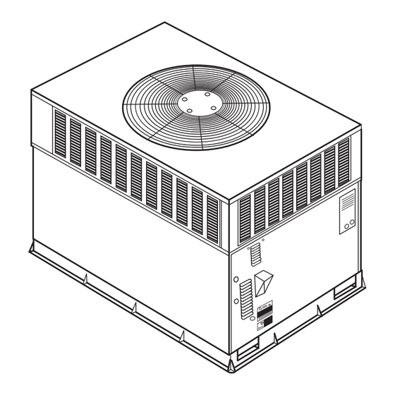
Fig. 1 - - Unit 574B
. . . . . . . . . . . . . . . . . . . . . . . . . . . . . . . . . . . .
. . . . . . . . . . . . . . . . . . . . . . . . . . . . . . . . . .
. . . . . . . . . . . . . . . . . . . . . . . . . . . . . . . . . . .
. . . . . . . . . . . . . . . . . . . . . . . . . . . . . . . . . .
. . . . . . . . . . . . . . . . . . . . . .
. . . . . . . . . . . . . . . . . . . . . . . . . . . . . . . .
. . . . . . . . . . . . . . . . . . . . . . . . . . . . . . .
. . . . . . . . . . . . . . . . . . . . . . . . . . . . . . . . . . .
. . . . . . . . . . . . . . . . . . . . . . . . . . . . .
. . . . . . . . . . . . . . . . . . . . . . . . . . .
C99088B
23
23
23
24
24
25
25
26
26
26
27
27
Advertisement
Table of Contents

Related Manuals for Bryant 574B


Summary of Contents for Bryant 574B
-
Page 1: Table Of Contents
....... . . C99088B Fig. 1 - - Unit 574B Install Duct Connections . -
Page 2: Introduction
INTRODUCTION GROUND MOUNT The 574B unit (see Fig. 1) is a fully self- -contained, combination Category I gas heating/electric cooling unit designed for outdoor The unit may be installed either on a slab or placed directly on the installation (See Fig. - Page 3 REQ’D CLEARANCES FOR OPERATION AND SERVICING. in. (mm) REQ’D CLEARANCES TO COMBUSTIBLE MAT’L. in. (mm) Evaporator coil access side ....36 (914) Top of unit ......14 (355.6) Power entry side (except for NEC requirements) .
-
Page 4: Provide Clearances
REQUIRED CLEARANCE FOR OPERATION AND SERVICING REQUIRED CLEARANCE TO COMBUSTIBLE MATL. in. [mm] in. [mm] EVAP. COIL ACCESS SIDE..............36.00 [914.0] TOP OF UNIT...................14.00 [355.6] POWER ENTRY SIDE..............36.00 [914.0] DUCT SIDE OF UNIT.................2.00 [50.8] (EXCEPT FOR NEC REQUIREMENTS) SIDE OPPOSITE DUCTS ..............14.00 [355.6] UNIT TOP ..................36.00 [914.0] BOTTOM OF UNIT ................0.50 [12.7] SIDE OPPOSITE DUCTS ..............36.00 [914.0]... - Page 5 HVAC unit HVAC unit base base Gask eting inner flange* Scre w Scre w Gask eting (NO TE A) (NO TE A) inner flange* *Gask eting *Gask eting outer flange outer flange Wood nailer* Wood nailer* Flashing field Flashing field supplied supplied Roofcurb*...
- Page 6 Corner Weight 1 Corner Weight 2 Corner Weight 2 Corner Weight 3 Corner Weight 3 Corner Weight 4 Corner Weight 4 Fig. 5 - - 574B Corner Weights 914-1371 (36”-54”) DUCTS 927.57 (36”-52”) SEAL STRIP MUST BE IN PLACE BEFORE PLACING 1226.3...
-
Page 7: Connect Condensate Drain
UNIT FALLING HAZARD Model 574B disposes of condensate water through a 3/4 in. NPT Failure to follow this warning could result in personal injury fitting which exits through the compressor access panel (See Fig. -
Page 8: Install Flue Hood
Table 1 – Physical Data - - Unit 574B (Continued) UNIT SIZE 574B 048090 048115 048130 060090 060115 060130 NOMINAL CAPACITY (ton) OPERATING WEIGHT (lb.) COMPRESSORS Scroll Quantity REFRIGERANT (R ---410A) Quantity (lb.) 11.5 11.5 11.5 13.5 13.5 13.5 REFRIGERANT METERING DEVICE CONDENSER COIL Rows...Fins/in. -
Page 9: Install Gas Piping
Table 2 – Maximum Gas Flow Capacity* NOMINAL INTERNAL LENGTH OF PIPE, FT† IRON PIPE, DIAMETER SIZE (IN.) (IN.) .622 — — .824 1.049 11/4 1.380 1400 11/2 1.610 2100 1460 1180 * Capacity of pipe in cu ft of gas per hr for gas pressure of 0.5 psig or Protection Association NFPA 54. less. Pressure drop of 0.5--in. wc (based on a 0.60 specific gravity gas). -
Page 10: Configuring Units For Downflow (Vertical)
CONFIGURING UNITS FOR DOWNFLOW (VERTICAL) DISCHARGE WARNING ELECTRICAL SHOCK HAZARD Failure to follow this warning could result in personal injury or death. Before installing or servicing system, always turn off main power to system. There may be more than one disconnect switch. -
Page 11: Install Electrical Connections
7. Flash, weatherproof, and vibration- -isolate all openings in building structure in accordance with local codes and good HIGH VOLTAGE building practices. POWER LEADS POWER (SEE UNIT WIRING SUPPLY Step 10 — INSTALL ELECTRICAL CONNEC- LABEL) TIONS WARNING FIELD-SUPPLIED FUSED DISCONNECT CONTROL BOX ELECTRICAL SHOCK HAZARD BLK(DH) -
Page 12: Control Voltage Connections
Remove the rubber grommet from the INSTALLED installer’s packet and install grommet in the knockout opening. Factory selected on 574B for AC- -Air conditioner. Provide a drip loop before running wire through panel. Run the For Gas Heat/Electric Cool Unit- -AC must be selected. - Page 13 The following basic configuration of the indoor motor a. AUXILIARY TERMINALS The AUX and HUM will provide ARI rated performance of the 574B. This terminals on the Easy Select Board are tied directly to BASIC CONFIGURATION should be used when the the G terminal, and provide a 24- -v.
-
Page 14: Heat Anticipator Setting
Leak test all refrigerant tubing connections using A95316 electronic leak detector, halide torch, or liquid- -soap Fig. 14 - - Humidistat Wiring for De- -Humidify Mode - - 574B solution. If a refrigerant leak is detected, see the Check for Refrigerant Leaks section. -
Page 15: Check For Refrigerant Leaks
Step 2 — UNIT SEQUENCE OF OPERATION gas piping has been checked for leaks. CHECK HEATING CONTROL 574B Sequence of Operation Start and check the unit for proper cooling control operation as a. CONTINUOUS FAN follows (see furnace lighting instructions located inside burner or (1.) Thermostat closes circuit R to G- -The Blower... -
Page 16: Adjust Gas Input
ADJUST GAS INPUT and 3.6 in. wc. Unsafe operation of the unit may result if manifold pressure is outside this range. Personal injury or The gas input to the unit is determined by measuring the gas flow unit damage may result. at the meter or by measuring the manifold pressure. - Page 17 A07012 Fig. 18 - - 208/230- -1- -60 Wiring Diagram, Unit 574B...
- Page 18 A07013 Fig. 19 - - 208/230- -3- -60 Wiring Diagram, Unit 574B...
-
Page 19: Airflow And Temperature Rise
Table 3 – Heating Inputs GAS SUPPLY PRESSURE (IN. WC) HEATING NUMBER OF MANIFOLD PRESSURE (IN. WC) Natural Propane† INPUT (BTUH)* ORIFICES Natural Propane† 40,000 13.0 13.0 60,000 13.0 13.0 90,000 13.0 13.0 115,000 13.0 13.0 130,000 13.0 13.0 * When a unit is converted to propane, different size orifices must be used. See separate, natural--to--propane conversion kit instructions. †... - Page 20 Required Subcooling oF (oC) Required Liquid Line Temperature for a Specific Subcooling (R-410A) Outdoor Ambient Temperature Required Subcooling ( Required Subcooling ( Model Size 75 (24) 82 (28) 85 (29) 95 (35) 105 (41) Pressure Pressure (kPa) (psig) 10.3 ( 5.7 ) 9.8 ( 5.4 ) 9.4 ( 5.2 ) 9 ( 5 )
- Page 21 Table 7 – 574B Cooling Dry Coil ECM Airflow Small Cabinet CFM ADJUST PIN LO PIN NOM PIN HI PIN SELECT UNIT EXTERNAL STATIC SIZE PRESSURE RANGE 0.0–0.39 0.4–0.69 0.7–1.0 0.0–0.39 0.4–0.69 0.7–1.0 0.0–0.39 0.4–0.69 0.7–1.0 (in. wc) COOLING –...
-
Page 22: Checking And Adjusting Refrigerant Charge
MAINTENANCE IMPORTANT: Three- -phase, scroll compressor units are direction- -oriented. These units must be checked to ensure proper To ensure continuing high performance and to minimize the compressor 3- -phase power lead orientation. If not corrected possibility of premature equipment failure, periodic maintenance within 5 minutes, the internal protector shuts off the compressor. -
Page 23: Air Filter
5. Check and inspect heating section before each heating 3. Remove the 12 screws holding the flue collector box season. Clean and adjust when necessary. cover (See Fig. 24) to the heat exchanger assembly. Inspect the heat exchangers. 6. Check flue hood and remove any obstructions, if necessary. -
Page 24: Condenser Coil, Evaporator Coil, & Condensate Drain Pan
CONDENSER COIL, EVAPORATOR COIL, AND CONDENSATE DRAIN PAN Inspect the condenser coil, evaporator coil, and condensate drain BLOWER pan at least once each year. The coils are easily cleaned when dry; HOUSING therefore, inspect and clean the coils either before or after each cooling season. -
Page 25: Electrical Controls And Wiring
QUICK REFERENCE GUIDE SET-UP INSTRUCTIONS FOR EASY SELECT BOARD (SUPER HUMIDITY CONTROL IN COOLING) EASY SELECT BOARD 9 PIN CONNECTOR 1. Configuration Taps ECM PRINTED CIRCUIT BOARD (See Installation Instructions, for detailed description) A. HEAT RANGE - Set for gas heat size (EX: 090 for unit 048090---) B. -
Page 26: Gas Input
3. Apply ohm meter leads across switch. You should have REFRIGERANT SYSTEM continuity on a good switch. This information covers the refrigerant system of the 574B, NOTE: Because these switches are attached to refrigeration including the compressor oil needed, servicing systems on roofs... -
Page 27: Troubleshooting
PURON (R- -410A) REFRIGERANT CHARGING run- -offs, and protect drop cloth from tears caused by tools or components. Refer to unit information plate and charging chart. Some R- -410A 3. Place terry cloth shop towel inside unit immediately under refrigerant cylinders contain a dip tube to allow liquid refrigerant component(s) to be serviced and prevent lubricant to flow from cylinder in upright position. - Page 28 Table 12 – Troubleshooting Guide - - Cooling SYMPTOM CAUSE REMEDY Power failure Call power company Fuse blown or circuit breaker tripped Replace fuse or reset circuit breaker Defective contactor, transformer, or high--pressure, Replace component Compressor and condenser fan will not start. loss--of--charge or low--pressure switch Insufficient line voltage Determine cause and correct...
- Page 29 Table 13 – Troubleshooting Guide–Heating SYMPTOM CAUSE REMEDY Water in gas line Drain. Install drip leg. No power to furnace Check power supply fuses, wiring or circuit breaker. Check transformer. No 20--v power supply to control circuit NOTE: Some transformers have internal over--current protection that requires a cool--down period to reset.
- Page 30 Continous Fan C01999 Catalog No. II574B---24---4 E2007 Bryant Heating & Cooling Systems 7310 W. Morris St. Indianapolis, IN 46231 Printed in U.S.A. Edition Date: 01/07 Manufacturer reserves the right to discontinue, or change at any time, specifications or designs without notice and without incurring obligations.
Need help?
Do you have a question about the 574B and is the answer not in the manual?
Questions and answers