Table of Contents
Advertisement
Quick Links
SPC-ET Mounting Guidelines
SPC-ET PHOTOELECTRIC BEAM DETECTOR
MOUNTING GUIDELINES
When installing the SPC-ET Beam Detectors, it is important that the following guidelines are adhered to:
Do not mount in locations that are exposed to
extremely high temperatures or water vapour.
Do not mount SPC-ET within 300mm of any
obstruction.
Do not mount where the distance between the
Emitter and Receiver is less than 5 metres or greater
than 100 metres.
List of Parts
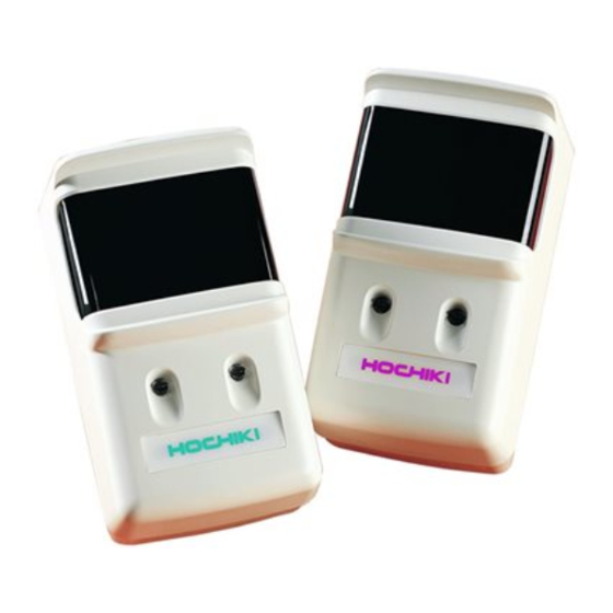
The SPC-ET Beam Detector kit consists of three separate parts: -
SPC-ET Receiver and Emitter.
SPC-ET Receiver and Emitter interface kit (including 2 way and 10 way ribbon cables).
Test Filters (25%, 50% and 60%) – located in packaging – DO NOT DISCARD.
Mounting the SPC-ET Beam Detector (c/w SPC-ET 2WI Interface Kit)
The SPC-ET Beam Detectors are designed to mount vertically onto Dual Gang back boxes (suggested type is Appleby
AL5136). These boxes should be fixed securely to the wall and directly opposite each other, they must also be mounted
the same distance from the ceiling at each end.
Wiring and Set Up
There are three main wiring methods available for the SPC-ET Beam Detector depending on the application. These are
shown below. In all methods, cables should be brought through the top of the back box, and terminated into the
appropriate connector blocks.
Fig.1
Hochiki Europe (UK) Ltd
Make sure the surface that the SPC-ET units are to
be mounted on is rigid (ideally part of the building
structure) to avoid any possibility of movement.
When fixing the SPC-ET allow enough space to gain
access to the sight hole for aligning purposes (this is
located on the top right hand side of the Receiver
unit, when viewed from the front).
Page 1
Method One
The Receiver is wired
directly to the zone from
the conventional panel.
The Emitter is powered
by a separate power
supply.
Method Two
The Receiver is wired
directly to the zone from
the conventional panel
and the Emitter is also
powered via the
1
conventional zone*
.
Method Three
The Receiver is wired
directly to the loop from
the analogue panel via a
CHQ-SZM Single Zone
2
Monitor*
. The Emitter
is powered by a
separate power supply,
but can also be powered
directly from the ESP
loop if required.
2-3-0-796/ISS6/SEPT13
Advertisement
Table of Contents

Related Manuals for Hochiki SPC-ET


Summary of Contents for Hochiki SPC-ET
- Page 1 Mounting the SPC-ET Beam Detector (c/w SPC-ET 2WI Interface Kit) The SPC-ET Beam Detectors are designed to mount vertically onto Dual Gang back boxes (suggested type is Appleby AL5136). These boxes should be fixed securely to the wall and directly opposite each other, they must also be mounted the same distance from the ceiling at each end.
- Page 2 If the line continuity option has NOT been selected, the power supply must be connected to the receiver first. The CHQ-Z Dual Zone Monitor can also be used to interface the SPC-ET to the analogue loop, but this device requires an additional auxiliary 24Vd.c.
- Page 3 25%, 50% and 60%. Bit 3 can be set to allow the SPC-ET to indicate fault and fire (OFF), or fault only (ON) on a total obscuration of the Beam. Bit 4 can be set to allow automatic reset (OFF) or manual reset (ON) from a fault condition. Please note that if the SPC- ET is set to show a non-latching fault on total obscuration and the SPC-ET beam is blocked for more than 30 minutes then the fault will LATCH.
- Page 4 25%, the range 2 filter relates to 50% and the range 3 filter relates to 60%. Firstly place the no alarm side of the filter in front of the SPC-ET for at least one minute this should cause no fire or fault signals, if a fault occurs the amber LED will flash once every 3 seconds.
Need help?
Do you have a question about the SPC-ET and is the answer not in the manual?
Questions and answers