Advertisement
SPC-E Mounting Guidelines
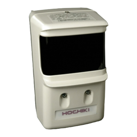
SPC-E PHOTOELECTRIC BEAM DETECTOR
MOUNTING GUIDELINES
When installing the SPC-E Beam Detectors, it is important that the following guidelines are adhered to:
Do not mount in locations that are exposed to
extremely high temperatures or water vapour.
Do not mount SPC-E within 300mm of any
obstruction.
Do not mount where the distance between the
Emitter and Receiver is less than 5 metres or greater
than 100 metres.
List of Parts
The SPC-E Beam Detector kit consists of three separate parts:
SPC-E Receiver and Emitter.
2 x four pronged Mounting Plates.
Test Filters (25%, 50% and 60%).
Mounting the SPC-E Beam Detectors
The SPC-E Beam Detectors are designed to mount vertically onto the four pronged mounting brackets supplied. These
brackets should be fixed securely to the wall and directly opposite each other, they must also be mounted in the same
horizontal plane.
There are several wiring methods available for the SPC-E, all of which are further explained in our Application Note
AP097 available from our website. The most common wiring method is shown below. In all methods, cables should be
brought through the top of the back box, and terminated into the appropriate connector blocks. The SPC-E Beam
Detectors require the use of an auxiliary 24Vd.c. Power Supply Unit (not supplied). The Power Supply and field wiring
should be terminated into the front of the SPC-E. Refer to Fig.1 if the panel requires a short-circuit to produce a fire
condition. If the panel requires a fire resistor refer to Fig 2.
Note: The Emitter can be powered directly from a local 24Vd.c. power supply, the Conventional zone or an ESP loop.
Hochiki Europe (UK) Ltd
Make sure the surface that the SPC-E units are to
be mounted on is rigid (ideally part of the building
structure) to avoid any possibility of movement.
When fixing the SPC-E allow enough space to gain
access to the sight hole for aligning purposes (this is
located on the top right hand side of the Receiver
unit, when viewed from the front).
Page 1
Fig.1
2-3-0-798/ISS2/MAR08
Advertisement
Table of Contents

Subscribe to Our Youtube Channel
Related Manuals for Hochiki SPC-E


Summary of Contents for Hochiki SPC-E
- Page 1 Detectors require the use of an auxiliary 24Vd.c. Power Supply Unit (not supplied). The Power Supply and field wiring should be terminated into the front of the SPC-E. Refer to Fig.1 if the panel requires a short-circuit to produce a fire condition.
- Page 2 SPC-E Mounting Guidelines Page 2 Starting at the emitter end, the cover should be opened (refer to Fig.3.) the field wiring can then be connected either from behind the detector or from below the detector, depending on the suitability of the installation.
- Page 3 The cover on the Receiver can now be closed (please refer to Fig.5.), this should be done carefully, avoiding the possibility of moving the SPC-E out of alignment. Fig.5 Closing the cover on the receiver synchronizes the receiver with the emitter, then automatically adjusts the amplification factor of the reception circuit, then initiates fire monitoring.
- Page 4 25%, the range 2 filter relates to 50% and the range 3 filter relates to 60%. Firstly place the no alarm side of the filter in front of the SPC-E for at least one minute this should cause no fire or fault signals, if a fault occurs the amber LED will flash once every 3 seconds.
Need help?
Do you have a question about the SPC-E and is the answer not in the manual?
Questions and answers