Table of Contents

Related Manuals for HEAVTH HF100


Summary of Contents for HEAVTH HF100
- Page 1 HF100 Capecitance Height Controler TECHNICAL MANUAL VISION:1302 CHANGZHOU HEAVTH SCIENCE&TECHNOLOGY CO.,LTD. 136# HUBIN ROAD NIUTANG TOWN CHANGZHOU CITY JIANGSU IN CHINA TEL:86-0519-89182619 FOX:86-0519-89183619 Http://www.heavth.com...
-
Page 2: Table Of Contents
HF100 CapecitanceHeightControler http://www.heavth.com TABLE OF CONTENTS ........ 5 IMPORTANT INFORMATION ....... 5 ERVICE SSISTANCE AND ONTACT NFORMATION ..............5 ECEIVING AND NPACKING ..............5 AFETY ONSIDERATIONS ..........5 NSTALLATION ONSIDERATIONS ................ 6 EPLACEMENT ARTS Part Names ..........................6 ONFIGURING THE... -
Page 3: Important Information
• Check to be sure that you have all of the required parts. Refer to P6 of this manual. • Familiarize yourself with the parts of the HF100 by reviewing P4 in this manual. • Check to be sure that the torch lifter motors you are using with the HF100 are within the acceptable range. -
Page 4: Part Names
HF100 CapecitanceHeightControler http://www.heavth.com 1.6 PARTS HF100 Part Names: HF100-L include: connector,high-frequency cable HF100-L include: connector,high-frequency cable,flexible coupling, torch clamp,ring sensor。 第 - 4 - 页 共 14 页... -
Page 5: Motor
Automatic control of the clearance span lets you make a smooth, quality cut at higher speeds with the least amount of dross. HF100 lets you achieve and maintain the optimum amount of cut clearance and can provide the following economical advantages: •... -
Page 6: Front Panel Components
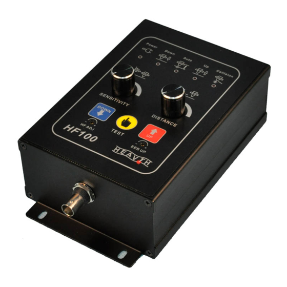
HF100 CapecitanceHeightControler http://www.heavth.com 2.1.1 FRONT PANEL COMPONENTS Connector X2 Connector X1 TO LIFTER TO CNC SENSITIVITY DISTANCE DOWN AUTO TEST HF Connector 第 - 6 - 页 共 14 页... -
Page 7: Modes
2.1.2.2 MANUAL MODE When the contacts of the Automatic/Manual switch are open, the HF100 is in Manual mode. The position of the torch is controlled using the Up/Down switches and the lifter moves at the maximum speed. When the Up/Down switch is released, the action of the lifter is stopped using dynamic braking to allow for exact manual positioning. - Page 8 Find a mounting location towards the side or back of the torch lifter unit. Choose a location for the HF100 that lets you access all four (4) of the screws that fasten the front cover control box to the back plate and completely remove the control box from the back panel.
- Page 9 Frequency/current 3.1.1 Collision output to CNC HF100 has Anti-collision function,it is effective on both manual/auto mode. When steel or other conductive item touches sensor ring, torch lift up, and the collision signal is sent out from the Pin3 of 7-pin socket(OC door), when CNC receives this signal, machine pauses and waits for treatment of collision.
- Page 10 HF100 CapecitanceHeightControler http://www.heavth.com HF100 Collision +24V Signal POWER Collision Signal Connection 3.1.2 SPEED CONTROLLER CLOCK FREQUENCY AND MAXIMUM MOTOR CURRENT Use the toggle switches on DIP switch SP2 to configure the speed controller clock frequency and maximum lifter motor current value.
-
Page 11: Start-Up Checks
Check to be sure that the measuring system is completely installed and correctly wired. Double-check to be sure that the: HF100 is connected to the sensor ring components by way of the appropriate HF 第 - 11 - 页 共 14 页... - Page 12 The following parts are connected to the protective conductor bus: machine earth ground (GND).torch table and ground screw on HF100 using a cable with a cross-section of 14 AWG (2.5 mm2). First, set on Manual mode, lift torch up over 20mm against steel plate.
-
Page 13: Drawings And Diagrams
HF100 CapecitanceHeightControler http://www.heavth.com 5 DRAWINGS AND DIAGRAMS 第 - 13 - 页 共 14 页... - Page 14 HF100 CapecitanceHeightControler http://www.heavth.com Collision Signal 第 - 14 - 页 共 14 页...
Need help?
Do you have a question about the HF100 and is the answer not in the manual?
Questions and answers