
Summary of Contents for Aerosonic OASIS
- Page 1 OASIS Standby Instrument System Installation Manual Aerosonic Corporation September 18, 2012 1212 N. Hercules Ave. Clearwater, FL 33765 USA...
- Page 2 INSTALLATION MANUAL OASIS Original Aerosonic Standby Instrument System Document No: Revision: X Title and Name Signature and Date Aerosonic Corporation September 18, 2012 1212 N. Hercules Ave. Clearwater, FL 33765 USA...
- Page 3 This page intentionally left blank OASIS Installation Manual...
- Page 4 Scope .......................... 6 2 ......................INSTALLATION ..........................6 UNPACKING AND INSPECTING ................6 INSTALLATION PROCEDURES ................. 6 2.2.1 Location ........................ 6 2.2.2 Electrical Connections ..................6 2.2.3 Installation ............. Error! Bookmark not defined. 2.2.4 Installation Guidelines for the SLZ7367..............19 OASIS Installation Manual...
- Page 5 This page intentionally left blank OASIS Installation Manual...
-
Page 6: General Description
Circular No. 43.1.-2B – Acceptable Methods, Techniques, and Practices – Aircraft Alterations must be followed. The information furnished is for convenience only. 1.2 Scope This manual applies to the installation of the OASIS standby display, remote sensor unit and the optional external magnetometer. 2 INSTALLATION 2.1 UNPACKING AND INSPECTING... - Page 7 Use of any cable not meeting specifications voids all warranties. 2. Refer to the appropriate Interconnect Wiring Diagram in Figures #-# and : 3. Wires and cables associated with the OASIS installation shall be fabricated from, Shielded cable shall be in accordance with MIL-C-27500 and non-shielded wire shall be in accordance with MIL-W-22759/16.
-
Page 8: Display Unit Installation
When locating the OASIS DU in the instrument panel, take the following information into consideration. 1. The OASIS DU should be located in an area where the softkey buttons are within easy reach of the pilot. 2. The OASIS should be accessible for inspection , maintenance, or removal and free from instrument panel structural flexure and excessive vibration or heat. - Page 9 3 DU D IGURE IMENSIONS OASIS Installation Manual...
- Page 10 Perform the following installation procedures to install the OASIS standby display. 5. See figures 4 and 5 for typical instrument panel mounting location for the Oasis DU. 4 TYPICAL FIXED WING INSTRUMENT PANEL IGURE 5 TYPICAL ROTARY WING INSTRUMENT PANEL...
- Page 11 6. The panel must be cutout if a suitable ATI-3 hole is not available, see Fig 6 for the Instrument cutout dimensions. 6 DU PANEL CUTOUT IGURE OASIS Installation Manual...
- Page 12 7. The Oasis DU is secured in the Instrument panel using a 69020-6 ARINC 408A mooring plate, see figure 7. 7 DU P IGURE ANEL NSTALL OASIS Installation Manual...
- Page 13 8. The Display Unit connector views are shown in Figure 8. The mating connector for the DU is D38999/26FD35S with a M85049/38s15 Strain Relief Clamp. IGURE DISPLAY UNIT CONNECTOR FACE VIEWS OASIS Installation Manual...
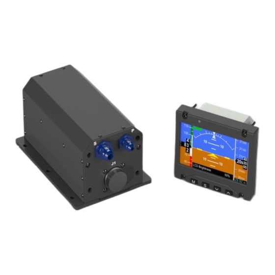
- Page 14 The Aerosonic Sensor Unit (ASU) is a separate remote mounted LRU that provides power and sensor data to the OASIS DU. The ASU is connected to the aircraft DC buss and powers up to two DU’s and a MCU. Sensors within the ASU provide for computation of Indicated Airspeed, Barometric Corrected Altitude, Pressure Altitude and slip/skid.
- Page 15 IGURE ASU DIMENSIONS OASIS Installation Manual...
- Page 16 For mounting dimensions for the ASU see Figure 11. IGURE ASU MOUNTING DIMENSIONS OASIS Installation Manual...
- Page 17 The ASU allowed orientations are as shown in Table 2 following 2 ALLOWED ASU ORIENTATIONS ABLE Orientation Bits Connector End ASU Mounting (3-0) Axis Surface 0000 0001 0010 0011 0100 0101 0110 0111 1000 1001 1010 1011 1100 1101 1110 1111 OASIS Installation Manual...
- Page 18 The Pitot fitting on the ASU is an AN4 Male fitting with MS33656-4 (7/16-20 thread for ¼” tubing). STATIC PORT CONNECTION The Static fitting on the ASU is an AN6 Male fitting with MS33656-6 (9/16-18 thread for 3/8” tubing). OASIS Installation Manual...
- Page 19 Note that the direction of flight (forward in the aircraft) is away from the cable assembly. Strain reliefs are provided at both the housing and connector. IGURE MAGNETIC SENSOR UNIT See Figure 14 for the dimensions of the MSU IGURE MSU DIMENSIONS OASIS Installation Manual...
- Page 20 This will prevent current flow in the wing skin that may degrade the performance of the MSU. OASIS Installation Manual...
- Page 21 The shielded cable can be extended to a maximum distance of 100 ft. The mating connector for the AHR150A-2-A cable is D38999/24JB98SN or equivalent, with a M85049/38S11 Strain Relief Clamp. See Figure 16 for the connector face views OASIS Installation Manual...
- Page 22 RS422 Rx A, Positive No Connect Factory Calibration & Field Calibration Only. RS422 Tx B, RS485 Tx/Rx B, Negative To the RS422 receiver B terminal or Negative RS485 Tx/Rx B . Power, Positive Power, Positive Power Supply 9 VDC (Nominal). OASIS Installation Manual...
-
Page 23: Appendix A: Suggested Lru Locations
APPENDIX A: SUGGESTED LRU LOCATIONS IGURE FIXED WING LRU LOCATIONS OASIS Installation Manual... - Page 24 IGURE ROTART WING LRU LOCATIONS OASIS Installation Manual...
-
Page 25: Appendix B: System Wiring Diagrams
APPENDIX B: System Wiring Diagrams IGURE SINGLE DU WIRING DIAGRAM OASIS Installation Manual... - Page 26 IGURE DUAL DU WIRING DIAGRAM OASIS Installation Manual...
-
Page 27: Appendix C: Weight And Balance
Connectors, etc. TOTAL REMOVED EQUIPMENT 5. The OASIS equipment is listed in Table. Insert the arms of the installed items in the appropriate cell of the ARM column. 6. Insert a weight for the install wire, cable, connectors and brackets 7. - Page 28 11. Calculate the total Moment change by subtracting the “Total Removed Equipment Moment” from the “Total Installed Equipment Moment”. 12. Enter these totals in the Total Change cells for Weight and Moment. 13. Update the aircraft empty weight and balance report to include the changes listed above. OASIS Installation Manual...
- Page 29 (battery, generator, alternator, etc.) and, the load on the bus used to power the OASIS is less than the maximum load approved for that bus. These maximum load capabilities are provided in the aircraft maintenance manuals.
Need help?
Do you have a question about the OASIS and is the answer not in the manual?
Questions and answers