
Related Manuals for Festo SBOC-M-R1B-H

Summary of Contents for Festo SBOC-M-R1B-H
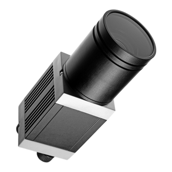
- Page 1 Compact Vision System Description Electronics Description Compact Vision System SBOC-M-R1B-H Description 8001260 en 1602a [8059462]...
- Page 3 ....... . . 8001260 E (Festo AG & Co. KG, D‐73726 Esslingen, 2012) Internet: http://www.festo.com E-Mail: service_international@festo.com...
- Page 4 Contents and general instructions Trademarks ® Harax is a registered trade mark of HARTING Electronics GmbH & Co. KG ® Harting RJ Industrial is a registered trade mark of HARTING Electronics GmbH & Co. KG Festo GDCS-SBOC-EN en 1602a...
- Page 5 ..........Structure of the Compact Vision System type SBOC-M-R1B-H .
- Page 6 ............Festo GDCS-SBOC-EN en 1602a...
- Page 7 The device is intended for use in an industrial environment. Measures may need to be implemented in residential areas for interference suppression. The Compact Vision System SBOC-M-R1B-H may only be used as follows: – only in an industrial environment –...
- Page 8 CE marking. Standards and test values, which the product complies with and fulfils, can be found in the Technical data section. The product-relevant EU directive can be found in the declaration of conformity. Festo GDCS-SBOC-EN en 1602a...
- Page 9 Mount the Compact Vision System in a well ventilated • location, especially screened from the heat emitted by other devices and from sources of light. Festo GDCS-SBOC-EN en 1602a...
- Page 10 – with an air gun or with clean non-lubricated compressed – with a soft moist cloth and non-abrasive cleaning agents. Service Please consult your local Festo repair service if you have any technical problems. Target group This description is intended exclusively for technicians trained in control and automation technology who have ex...
- Page 11 ... means that failure to observe this instruction may result in material damage. In addition, the following pictogram marks passages in the text which describe activities with electrostatically sensitive devices: Electrostatically sensitive devices: Incorrect handling may cause damage to devices. Festo GDCS-SBOC-EN en 1602a...
- Page 12 Recommendations, tips and references to other information sources. Accessories: Specifications on necessary or useful accessories for the Festo product. Environment: Information on the environmentally friendly use of Festo products. Text designations Bullet points indicate activities which may be carried out • in any sequence.
- Page 13 This description contains general basic information on mount ing, installation and operation of the Compact Vision System. Additional information on commissioning, parametrisation and diagnostics with the software package “Festo Configura tion Tool” can be found in the help system for the software. Type...
- Page 14 (see also sensor amplification). With mov ing objects, excessive exposure times result in blurred pictures. Festo Configuration Tool is the software package for configuring and commis sioning various components and devices from Festo...
- Page 15 Excessive amplification can lead to grained pictures. Sharpness See depth of focus TCP/IP Combination of the protocols TCP and IP, the most widely used protocol for communication via Ethernet. Tab. 0/3: Product-specific terms and abbreviations XIII Festo GDCS-SBOC-EN en 1602a...
- Page 16 Contents and general instructions Festo GDCS-SBOC-EN en 1602a...
- Page 17 System overview Chapter 1 System overview Festo GDCS-SBOC-EN en 1602a...
-
Page 18: Table Of Contents
..........Structure of the Compact Vision System type SBOC-M-R1B-H . -
Page 19: System Overview
1. System overview Structure of the Compact Vision System type SBOC-M-R1B-H Components The Compact Vision System type SBOC-M-R1B-H is an intelligent high-speed camera with integrated electronics for image processing and communication. It is contained in a compact and robust housing and offers: –... - Page 20 I/Os or by a PC. Compact Vision System SBOC-M-R1B-H PC with “Festo Configuration Tool” FCT Fig. 1/1: Direct networking with the PC Hub/switch Compact Vision System SBOC-M-R1B-H PC with “Festo Configuration Tool” FCT Fig. 1/1: Camera network Festo GDCS-SBOC-EN en 1602a...
-
Page 21: Characteristics
1) Only in combination with protective tubing supplied 2) Without protective tubing, lenses with CS-mount thread can also be used (see section 1.4). 3) Entocentric, telecentric or hypercentric lenses can also be used Tab. 1/2: Compact Vision System SBOC-M-R1B-H Festo GDCS-SBOC-EN en 1602a... -
Page 22: Mode Of Operation
1. System overview 1.2.1 Mode of operation The Compact Vision System type SBOC-M-R1B-H has a monochrome CMOS sensor. The camera pictures are processed in 256 grey tones. The available processing functions are integrated in the operating system (firmware) of the device. Even motion sequences at high speed can therefore also be registered and analysed with high accuracy. -
Page 23: Display And Connecting Elements
1. System overview Commissioning The Festo Configuration Tool (FCT) is used for commission ing and operation in combination with the plug-in “SBO..-M Network” (see also section 1.3). 1.2.2 Display and connecting elements Support ring of the protective tubing Shield tube... - Page 24 – Synchronisation with other Com pact Vision Systems of type SBO..-M-... – Communication with higher-order equipment, e.g. the PC – Output of data (e.g. film se quences, data analyses, etc.) Tab. 1/4: Connections of the Compact Vision System Festo GDCS-SBOC-EN en 1602a...
-
Page 25: Fct Software (Functional Overview)
1. System overview FCT software (functional overview) The Festo Configuration Tool (or briefly FCT) is used for com missioning and operation. FCT is the software interface for configuring and commissioning various components and equipment from Festo. It can run under the operating systems Windows®... -
Page 26: Lens Selection
CS-mount standard. If you use C-mount lenses without protective tubing, you must screw in a 5 mm spacer ring in place of the protective tubing, in order to guarantee correct support dimensions (accessories see A.2). 1-10 Festo GDCS-SBOC-EN en 1602a... - Page 27 : object distance (working distance) G : object size (size of field of vision) f : focal length B : image or sensor size 1) The horizontal dimension of the sensor is 6.3 mm. Tab. 1/6: Calculation formula 1-11 Festo GDCS-SBOC-EN en 1602a...
- Page 28 100 mm wide at a working distance of 200 mm. – A lens with a focal length of 25 generates a field of vision approx. 100 mm wide at a working distance of 400 mm. 1-12 Festo GDCS-SBOC-EN en 1602a...
- Page 29 Mounting Chapter 2 Mounting Festo GDCS-SBOC-EN en 1602a...
- Page 30 ............2.1.1 Dimensions of the Compact Vision System SBOC-M-R1B-H ..
-
Page 31: Mounting
The Compact Vision System may be damaged if it is handled incorrectly. Make sure that glass surfaces, lens elements and lenses • are not scratched or contaminated. Mount the Compact Vision System so that items passing • by do not touch the device. Festo GDCS-SBOC-EN en 1602a... -
Page 32: Dimensions Of The Compact Vision System Sboc-M-R1B-H
2. Mounting 2.1.1 Dimensions of the Compact Vision System SBOC-M-R1B-H Fig. 2/1: Dimensions SBOC-M-R1B-H with protective tubing 2.1.2 Mounting the Compact Vision System On the bottom of the device, there is a mounting profile with dovetail guide. The following adapter kits can be used for... -
Page 33: Attachment With Adapter Kit Type Sboa-Hmsv-39
Proceed with mounting as follows: Place the Compact Vision System so that the field of vis • ion is unhindered and the LEDs on the rear of the housing can be seen. Tighten the screws evenly. • Festo GDCS-SBOC-EN en 1602a... -
Page 34: Mounting/Dismantling Of Lens And Protective Tubing
3. Now carefully guide the lens into the fixture of the sup port ring and screw it in clockwise by hand as well. 4. Carefully guide the shield tube (see Fig. 1/2, 2 ) over the lens and screw it clockwise by hand into the support ring. Festo GDCS-SBOC-EN en 1602a... - Page 35 Turn the shield tube anti-clockwise out of the fixture and • pull it forwards. Dimantling the lens Turn the lens anti-clockwise and pull it forwards out of the • fixture. Attach the protective cover to the lens and the camera • housing. Festo GDCS-SBOC-EN en 1602a...
- Page 36 2. Mounting Festo GDCS-SBOC-EN en 1602a...
- Page 37 Installation Chapter 3 Installation Festo GDCS-SBOC-EN en 1602a...
- Page 38 ..3.2.2 Connecting the Ethernet interface ......3-10 Festo GDCS-SBOC-EN en 1602a...
-
Page 39: Installation
Caution Cables with high noise levels can cause electromagnetic interference. Do not place the control cables in the vicinity of such • cables. If necessary, use separate wiring channels, sep arate cable bundles or separate cables. Festo GDCS-SBOC-EN en 1602a... - Page 40 EMER GENCY STOP (e.g. switching off the operating voltage for the valves and output modules, switching off the com pressed air). Festo GDCS-SBOC-EN en 1602a...
-
Page 41: Selection Of The Power Supply Unit
Simple 24 V transformers with rectifier and electrolytic capa citors achieve output voltages of 28 V and more with low loads. Correct operation can only be guaranteed if the permit ted operating voltage range is not exceeded (see Technical data in appendix A.4). Festo GDCS-SBOC-EN en 1602a... -
Page 42: Electrical Connections
Operating voltage supply and digital I/Os (plug M12x1) Fig. 3/1: Electrical connections of the Compact Vision System SBOC-M-R1B-H 3.2.1 Connection of the operating voltage supply and the I/Os Caution Damage to components! Make sure that the permissible operating voltage range •... - Page 43 EMC directives: Use only one of the following cables with sockets from • Festo for connecting the operating voltage supply and the inputs/outputs (see Tab. 3/2). Connect the screening of the cable with socket on the •...
- Page 44 Operating voltage connection and I/Os on the 8-pin M12 plug “24 V DC” You can establish the trigger input and trigger condition with the FCT and the plug-in “SBO..-M Network”. Additional information on this can be found in the help for the plug-in “SBO..-M Network”. Festo GDCS-SBOC-EN en 1602a...
- Page 45 Trigger input E0 is unused here Fig. 3/2: Example with use of a positive trigger signal at E1 With the configuration software Festo Configuration Tool (FCT), you determine whether a positive or negative edge should be used as a trigger signal.
-
Page 46: Connecting The Ethernet Interface
If in doubt, ask your network administrator whether cor • responding band widths are available for you or what an optimum network structure for you should look like. Comply with the necessary system requirements. • 3-10 Festo GDCS-SBOC-EN en 1602a... - Page 47 Cables and plug connectors for special requirements are commercially available - e.g. from Franz Binder GmbH & Co. (product program series 825) or from HARTING Electronics GmbH & Co. KG (product program Harax® M12 or Harting RJ Industrial®). 3-11 Festo GDCS-SBOC-EN en 1602a...
- Page 48 If the Ethernet cable is used with a fixed Ethernet building installation, correct earthing of the Ethernet cable will nor mally exist. In combination with mobile equipment, additional earthing measures at the Ethernet cable may be necessary to comply with electromagnetic compatibility (EMC) require ments. 3-12 Festo GDCS-SBOC-EN en 1602a...
- Page 49 (AUTO MDI-X), you will also require with the original cable a crossover cable and a cable coupling (see also Tab. 3/4). Original cable type SBOA-K30E-M12S Crossover cable Cable coupling Fig. 3/3: Direct connection with the PC 3-13 Festo GDCS-SBOC-EN en 1602a...
- Page 50 3. Installation 3-14 Festo GDCS-SBOC-EN en 1602a...
- Page 51 Commissioning Chapter 4 Commissioning Festo GDCS-SBOC-EN en 1602a...
- Page 52 ......... . . 4-16 Festo GDCS-SBOC-EN en 1602a...
-
Page 53: Commissioning
The plug-in for the Compact Vision System is installed on your PC together with the installation program of the FCT. For the Compact Vision System SBOC-M-R1B-H with the firmware version 2.0 or higher, you will need the following software versions: –... -
Page 54: Steps For Commissioning
1. Connect the Compact Vision System via the Ethernet inter face to your PC or hub/switch. Follow the instructions in chapter 3. 2. Start the FCT: double click on the Festo Configuration Tool icon on the Desktop – or –... - Page 55 4. Commissioning Additional information on the functions of the plug-in SBO..-M Network can be found in the plug-in help: command [Help] [Contents of installed plug-ins] [Festo (manufacturer name)] [SBO...-M Network (plug-in name)] e.g.: – on the description of the dialogues of “Device SBO..-M-...”...
-
Page 56: Addressing In The Ethernet (Basic Principles)
The IP address therefore con tains: – the net ID (specifies the address of a network) and – the host ID (specifies the address of an individual station in this network). Festo GDCS-SBOC-EN en 1602a... - Page 57 Which numbers in an IP address now represent the net ID and the host ID are defined by the specification of a so- called “net mask”. The telephone number of Festo Germany can be used as an example to explain the IP address and the net mask: 00497113470...
- Page 58 IP address – IP net mask – IP address of the gateway Note The following is preset at the factory: – IP address: 192.168.2.10 – IP net mask: 255.255.0.0 – IP address of the gateway: - Festo GDCS-SBOC-EN en 1602a...
-
Page 59: Instructions For Use Of A Firewall
Configuration Tool always has free access to the network connections. After installation of the Festo Configuration Tool, if you have an active firewall, you automatically receive a safety warning from Windows when you try to build up a connection to the camera network for the first time. -
Page 60: Making Network Settings With The Compact Vision System
You must also adapt the characteristics of the device search (search range and search duration) corres pondingly. If you have any questions, consult your system administrator. 4-10 Festo GDCS-SBOC-EN en 1602a... - Page 61 If the network connections of your PC are protected • through a firewall: Check the configuration of the firewall of your PC. Configure the firewall so that the Festo Config uration Tool always has free access to the network con nections.
- Page 62 PC. If you have any questions, consult your system administrator. Note Additional information on IP addressing can be found in the help for the plug-in “SBO..-M Network” of the software package Festo Configuration Tool (FCT). 4-12 Festo GDCS-SBOC-EN en 1602a...
-
Page 63: Instructions On Operation
Data processing is limited. The error status is indicated. Caution Further heating beyond this point can lead to uncontrolled malfunctions. Make sure that the permissible temperature range is • complied with (see Technical data). 4-13 Festo GDCS-SBOC-EN en 1602a... -
Page 64: Setting The Optics
The segments run to the centre but do not overlap. Cameras cannot reproduce optimally the centre of such a test picture. An unsharp range will be visible, the so-called grey ring. The smaller the grey ring, the better the lens is focused. 4-14 Festo GDCS-SBOC-EN en 1602a... - Page 65 4. Commissioning Focusing object – with standard lens from Festo Loosen the clamping screw on the lens. • In order to focus the object, turn the focusing ring. • Tighten the clamping screw again slightly. • Setting aperture – with standard lens from Festo Loosen the clamping screw on the lens.
-
Page 66: Trigger Signal
The trigger signal is applied through one of the two inputs (I0 or I1). Trigger input and trigger condition are adjustable via the configuration software Festo Configuration Tool (FCT). The trigger condition is either a positive or a negative edge on the selected trigger input. - Page 67 Diagnostics and error handling Chapter 5 Diagnostics and error handling Festo GDCS-SBOC-EN en 1602a...
- Page 68 ........Festo GDCS-SBOC-EN en 1602a...
-
Page 69: Diagnostics And Error Handling
Look at error message with the FCT software package LED is flash ing red Undefined status, e.g.oper Check the operating voltage connec ating voltage not applied tion of the electronics LED is off Tab. 5/1: Operating status LED (A) Festo GDCS-SBOC-EN en 1602a... - Page 70 Meaning / error handling Illuminated at each record – ing for at least 250 ms LED illumin ated red Illuminated for 250 ms – when trigger signal is ap plied LED illumin ated yellow Tab. 5/3: Recording LED (C) Festo GDCS-SBOC-EN en 1602a...
- Page 71 Compact Vision Sys there is a connection to the FCT. LED is flash ing red Device is waiting for trigger – signal (ready for recording) LED is flash ing yellow Tab. 5/4: Recording status LED (D) Festo GDCS-SBOC-EN en 1602a...
-
Page 72: Error Elimination
– The object moves too quickly. Reduce exposure time • – The motif lies outside the fo Comply with the minimum • cal range. distance (see specifications on the lens) – Lens not focused Focus the lens • Festo GDCS-SBOC-EN en 1602a... - Page 73 239.255.2.3. If in doubt consult your system administrator. Windows error message – Insufficient free virtual Comply with the system re • memory quirements (see help for the plug-in “SBO..-M network”) Tab. 5/5: Error elimination Festo GDCS-SBOC-EN en 1602a...
- Page 74 5. Diagnostics and error handling Festo GDCS-SBOC-EN en 1602a...
- Page 75 Technical appendix Appendix A Technical appendix Festo GDCS-SBOC-EN en 1602a...
- Page 76 ..........Festo GDCS-SBOC-EN en 1602a...
-
Page 77: Technical Appendix
– with a soft moist cloth and non-abrasive cleaning agents. Clean the device if it is dirty. • Permissible cleaning agents are soap suds (max. +60 °C) and all non-abrasive agents. Festo GDCS-SBOC-EN en 1602a... -
Page 78: Accessories (At Press Time
SBOA-K30E-M12S Cable Ethernet cable for brief use as a diagnostic cable – Straight socket, M12, 4-pin, d-coded – RJ-45 Ethernet plug – Length 3 m Focal length è www.festo.com/catalogue SASF-C-L-F… Lens Cable coupling for RJ45 plug connector Crossover cable SBOA-HMSV-39... -
Page 79: Siemens Star
A. Technical appendix Siemens star Fig. A/1: Siemens star Festo GDCS-SBOC-EN en 1602a... - Page 80 With protective tubing: 139.4 Dimensions – Product weight Approx. 182 Ethernet interface – Bus interface IEEE802.3U (100BaseT) – Connector plug Plug, M12 – Transmission speed [Mbps] – Supported protocols TCP/IP Tab. A/2: Technical data (part 1) Festo GDCS-SBOC-EN en 1602a...
- Page 81 – Note on materials Free of copper and PTFE The device is intended for use in industrial environments. Measures may need to be implemented in residential areas for interference suppression. Tab. A/3: Technical data (part 2) Festo GDCS-SBOC-EN en 1602a...
- Page 82 A. Technical appendix Festo GDCS-SBOC-EN en 1602a...
- Page 83 Index Appendix B Index Festo GDCS-SBOC-EN en 1602a...
- Page 84 ............Festo GDCS-SBOC-EN en 1602a...
- Page 85 Error elimination ........Festo GDCS-SBOC-EN en 1602a...
- Page 86 ........Festo GDCS-SBOC-EN en 1602a...
- Page 87 ........VIII Festo GDCS-SBOC-EN en 1602a...
-
Page 88: Technical Data
......... Working distance ....... 1-11 Festo GDCS-SBOC-EN en 1602a...
Need help?
Do you have a question about the SBOC-M-R1B-H and is the answer not in the manual?
Questions and answers